


15-10
Catalyst 2950 and Catalyst 2955 Switch Software Configuration Guide
OL-10101-02
Chapter 15 Configuring Optional Spanning-Tree Features
Understanding Optional Spanning-Tree Features
to the root switch). Under spanning-tree rules, the switch ignores inferior BPDUs for the configured
maximum aging time specified by the spanning-tree vlan vlan-id max-age global configuration
command.
The switch tries to determine if it has an alternate path to the root switch. If the inferior BPDU arrives
on a blocked port, the root port and other blocked ports on the switch become alternate paths to the root
switch. (Self-looped ports are not considered alternate paths to the root switch.) If the inferior BPDU
arrives on the root port, all blocked ports become alternate paths to the root switch. If the inferior BPDU
arrives on the root port and there are no blocked ports, the switch assumes that it has lost connectivity
to the root switch, causes the maximum aging time on the root port to expire, and becomes the root
switch according to normal spanning-tree rules.
If the switch has alternate paths to the root switch, it uses these alternate paths to send a root link query
(RLQ) request. The switch sends the RLQ request on all alternate paths to the root switch and waits for
an RLQ reply from other switches in the network.
If the switch determines that it still has an alternate path to the root, it expires the maximum aging time
on the port that received the inferior BPDU. If all the alternate paths to the root switch indicate that the
switch has lost connectivity to the root switch, the switch expires the maximum aging time on the port
that received the RLQ reply. If one or more alternate paths can still connect to the root switch, the switch
makes all ports on which it received an inferior BPDU its designated ports and moves them from the
blocking state (if they were in the blocking state), through the listening and learning states, and into the
forwarding state.
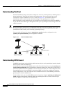
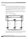
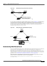
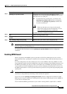
Figure 15-7 shows an example topology with no link failures. Switch A, the root switch, connects
directly to Switch B over link L1 and to Switch C over link L2. The Layer 2 interface on Switch C that
connects directly to Switch B is in the blocking state.
Figure 15-7 BackboneFast Example Before Indirect Link Failure
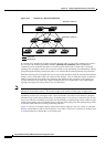
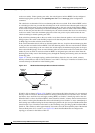
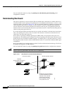
If link L1 fails as shown in Figure 15-8, Switch C cannot detect this failure because it is not connected
directly to link L1. However, because Switch B is directly connected to the root switch over L1, it detects
the failure, elects itself the root, and begins sending BPDUs to Switch
C, identifying itself as the root.
When Switch
C receives the inferior BPDUs from Switch B, Switch C assumes that an indirect failure
has occurred. At that point, BackboneFast allows the blocked port on Switch
C to move immediately to
the listening state without waiting for the maximum aging time for the port to expire. BackboneFast then
transitions the Layer 2 interface on Switch
C to the forwarding state, providing a path from Switch B to
Switch
A. This switchover takes approximately 30 seconds, twice the Forward Delay time if the default
Forward Delay time of 15 seconds is set.
Figure 15-8 shows how BackboneFast reconfigures the
topology to account for the failure of link L1.
L1
L2 L3
Switch C
Switch A
(Root)
Switch B
Blocked port
44963