


14-4
Catalyst 2950 and Catalyst 2955 Switch Software Configuration Guide
OL-10101-02
Chapter 14 Configuring MSTP
Understanding MSTP
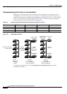
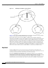
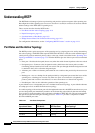
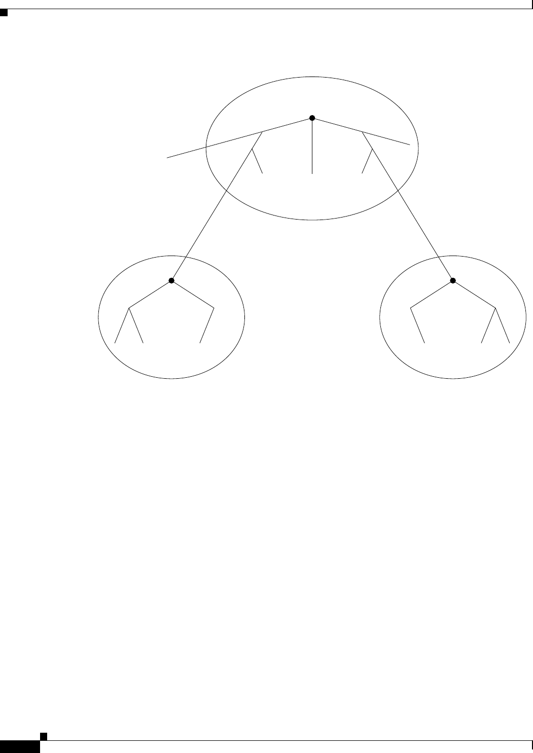
Figure 14-1 MST Regions, IST Masters, and the CST Root
Figure 14-1 does not show additional MST instances for each region. Note that the topology of MST
instances can be different from that of the IST for the same region.
Only the CST instance sends and receives BPDUs, and MST instances add their spanning-tree
information into the BPDUs to interact with neighboring switches and compute the final spanning-tree
topology. Because of this, the spanning-tree parameters related to BPDU transmission (for example,
hello time, forward time, max-age, and max-hops) are configured only on the CST instance but affect all
MST instances. Parameters related to the spanning-tree topology (for example, switch priority, port
VLAN cost, port VLAN priority) can be configured on both the CST instance and the MST instance.
MSTP switches use version 3 RSTP BPDUs or IEEE 802.1D STP BPDUs to communicate with legacy
IEEE 802.1D switches. MSTP switches use MSTP BPDUs to communicate with MSTP switches.
Hop Count
The IST and MST instances do not use the message-age and maximum-age information in the
configuration BPDU to compute the spanning-tree topology. Instead, they use the path cost to the root
and a hop-count mechanism similar to the IP time-to-live (TTL) mechanism.
By using the spanning-tree mst max-hops global configuration command, you can configure the
maximum hops inside the region and apply it to the IST and all MST instances in that region. The hop
count achieves the same result as the message-age information (determines when to trigger a
reconfiguration). The root switch of the instance always sends a BPDU (or M-record) with a cost of 0
and the hop count set to the maximum value. When a switch receives this BPDU, it decrements the
IST master
and CST root
IST master IST master
A
MST Region 1
D
Legacy 802.1D
B
MST Region 2 MST Region 3
C
74009