


1-16
Catalyst 2950 and Catalyst 2955 Switch Software Configuration Guide
OL-10101-02
Chapter 1 Overview
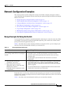
Network Configuration Examples
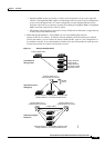
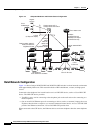
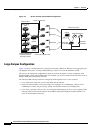
Figure 1-3 Collapsed Backbone and Switch Cluster Configuration
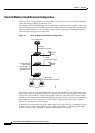
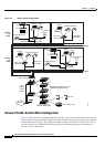
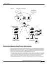
Hotel Network Configuration
Figure 1-4 shows Catalyst 2950ST-8 LRE and 2950ST-24 LRE switches in a hotel network environment
with approximately 200 rooms. This network includes a PBX switchboard, a router, and high-speed
servers.
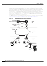
Connected to the telephone line in each hotel room is an LRE CPE device, such as a Cisco LRE CPE
device. The LRE CPE device provides:
• Two RJ-11 ports, one for connecting to the telephone jack on the wall and one for connecting to a
POTS telephone.
• One or more RJ-45 Ethernet ports for connecting to devices such as a customer’s laptop, the room
IP phone, the television set-top box, or a room environmental control device. A Cisco
575 LRE CPE
provides one Ethernet connection; a Cisco
585 LRE CPE provides four.
When connected to the CPE device, the Ethernet devices and room telephone share the same telephone
line.
IP
IP
IP
IP
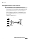
Catalyst 3550-12T or
Catalyst 3550-12G switch
200 Mbps
Fast EtherChannel
(400-Mbps full-duplex
Fast EtherChannel)
Gigabit
servers
Cisco
CallManager
60994
Cisco 2600 router
1 Gbps
(2 Gbps full duplex)
Cisco
IP Phones
Cisco IP Phones
Workstations running
Cisco SoftPhone software
Catalyst
2950,
2900 XL,
3550, and
3500 XL
GigaStack cluster
Catalyst 3550-24PWR
cluster
Catalyst 2950, 2900 XL,
3550, and 3500 XL
GigaStack cluster
IP
Si