


29-37
Catalyst 2950 and Catalyst 2955 Switch Software Configuration Guide
OL-10101-02
Chapter 29 Configuring QoS
Standard QoS Configuration Examples
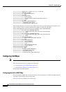
Standard QoS Configuration Examples
Note These examples are applicable only if your switch is running the EI.
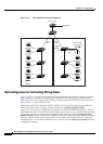
This section shows a QoS migration path to help you quickly implement QoS features based on your
existing network and planned changes to your network, as shown in
Figure 29-5. It contains this
information:
• QoS Configuration for the Existing Wiring Closet, page 29-38
• QoS Configuration for the Intelligent Wiring Closet, page 29-39
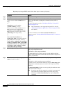
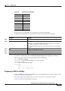
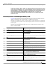
show mls qos maps [cos-dscp | dscp-cos] Display QoS mapping information. Maps are used to generate an
internal DSCP value, which represents the priority of the traffic.
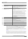
show mls qos interface [interface-id] [policers] Display QoS information at the interface level, including the
configuration of the egress queues and the CoS-to-egress-queue
map, which interfaces have configured policers, and ingress
statistics.
show mls masks [qos | security] Display details regarding the masks
1
used for QoS and security
ACLs.
show wrr-queue cos-map Display the mapping of the CoS priority queues.
show wrr-queue bandwidth Display the WRR bandwidth allocation for the CoS priority
queues.
1. Available only on a switch running the EI.
2. Access control parameters are called masks in the switch CLI commands and output.
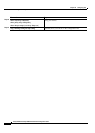
Table 29-9 Commands for Displaying QoS Information (continued)
Command Purpose