


29-3
Catalyst 2950 and Catalyst 2955 Switch Software Configuration Guide
OL-10101-02
Chapter 29 Configuring QoS
Understanding QoS
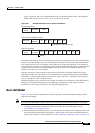
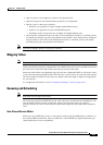
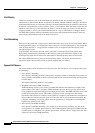
Layer 3 IP packets can carry a Differentiated Services Code Point (DSCP) value. The supported
DSCP values are 0, 8, 10, 16, 18, 24, 26, 32, 34, 40, 46, 48, and 56.
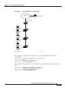
Figure 29-1 QoS Classification Layers in Frames and Packets
All switches and routers that access the Internet rely on the class information to give the same forwarding
treatment to packets with the same class information and different treatment to packets with different
class information. The class information in the packet can be assigned by end hosts or by switches or
routers along the way, based on a configured policy, detailed examination of the packet, or both. Detailed
examination of the packet is expected to happen closer to the edge of the network so that the core
switches and routers are not overloaded.
Switches and routers along the path can use the class information to limit the amount of resources
allocated per traffic class. The behavior of an individual device when handling traffic in the DiffServ
architecture is called per-hop behavior. If all devices along a path have a consistent per-hop behavior,
you can construct an end-to-end QoS solution.
Implementing QoS in your network can be a simple or complex task and depends on the QoS features
offered by your internetworking devices, the traffic types and patterns in your network, and the
granularity of control that you need over incoming and outgoing traffic.
Basic QoS Model
Figure 29-2 shows the basic QoS model. Actions at the ingress interface include classifying traffic,
policing, and marking:
Note If you have the SI installed on your switch, only the queueing and scheduling features are available.
• Classifying distinguishes one kind of traffic from another. For more information, see the
“Classification” section on page 29-4.
• Policing determines whether a packet is in or out of profile according to the configured policer, and
the policer limits the bandwidth consumed by a flow of traffic. The result of this determination is
passed to the marker. For more information, see the
“Policing and Marking” section on page 29-6.
111386
Encapsulated Packet
Layer 2
header
IP header Data
Layer 2 802.1Q and 802.1p Frame
Preamble
Start frame
delimiter
DA
Len
SA Ta g PT Data FCS
Layer 3 IPv4 Packet
Version
length
ToS
(1 byte)
ID Offset TTL Proto FCS IP-SA IP-DA Data
3 bits used for CoS (user priority)
DSCP