


12-7
Catalyst 2950 and Catalyst 2955 Switch Software Configuration Guide
OL-10101-02
Chapter 12 Configuring LRE
Understanding LRE Features
CPE toggle cannot be disabled on a Cisco 575 LRE or Cisco 576 LRE 997 CPE link but can be
disabled on a Cisco 585 LRE CPE. For more information, see the
“Configuring CPE Toggle” section
on page 12-21.
Use the show controllers ethernet-controller privileged EXEC command to display the internal switch
statistics, the statistics collected by the LRE switch interface, and the statistics collected by the LRE CPE
interface. For information about this command, see the command reference for this release.
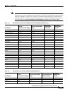
LRE Link Monitor
When the link monitor feature is enabled, an LRE switch tracks undesirable or interesting conditions on
a link and takes system-defined actions after certain thresholds are reached. The link monitor can track
these conditions:
• SNR, in dB: The link must have a minimum SNR to function; a higher SNR value means a better
noise margin on the link. Links are not established if the SNR is insufficient. For more information,
see the
“Link Qualification and SNR Margins” section on page 12-16.
• Reed-Solomon (RS) errors: The RS Forward Error Correction circuit corrects small bursts of errors
so that noise events do not cause Ethernet frame check sequence (FCS) errors. This is implemented
in the octal chip as a 32-bit counter. The count resets on read.
• Transmit (TX) Power, in dBm/Hz: This is fixed for the switch and adjusts automatically for the CPE
device. The local transmit power is always constant and the same for a given profile. The remote
transmit power varies according to distance from the switch to the CPE device, with a minimum
transmit power of 91.9 dBm/Hz (corresponding to short distances) and a maximum transmit power
of –55 dBm/Hz (corresponding to longer cable lengths or greater cable attenuation). The CPE device
power can reach its maximum at distances between 1500 feet (450 meters) and 3000 feet
(900
meters).
• Software Controlled Automatic Gain Control (SW AGC Gain), in dBm: This gives an indirect
measure of the received power level. Higher values mean that the receive power is lower (and thus
in need of more boost).
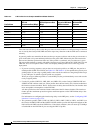
• Link Fail Counts: The number of times the link failed. A failed link interrupts operation of the
Ethernet link for a small number of milliseconds. During this interruption, some packets might be
dropped (depending on traffic levels).
• PMD Freeze Event Counter: This counts the occurrence of micro-interruption or saturation events.
Micro-interruptions and Analog to Digital Converter (ADC) saturations are caused by impulse noise
for a short duration. This is implemented in the octal chip as a 8-bit counter.
The link parameters need to be monitored both for the upstream and downstream directions.
You can use the information that you get from the link monitor to log events, set traps, change to a lower
rate profile, and disable the automatic power back-off feature.
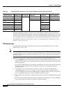
LRE Message Logging Process
The Catalyst 2950 LRE switch software monitors switch conditions on a per-port basis and sends the
debugging messages to an LRE message logging process that is different than the system message
logging process described in
Chapter 26, “Configuring System Message Logging.”
These options are available in the LRE logging process:
• Disabled—The switch does not log LRE events.