


12-4
Catalyst 2950 and Catalyst 2955 Switch Software Configuration Guide
OL-10101-02
Chapter 12 Configuring LRE
Understanding LRE Features
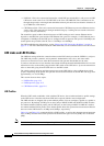
Your data rates will always be less than the gross data rate listed in tables. A small percentage of the link
rate is used by the Catalyst 2950 LRE switch for supervisory functions with the CPE device connected
remotely.
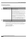
In general, profiles are named for the data rate that you expect to achieve and not the gross data rate as
given in the table. All system-defined profiles have the prefix LRE, followed by the downstream user
data rate and then the upstream user data rate. If the profile is symmetric, only one data rate is given.
The two profiles defined to comply with public frequency usage plans 998 and 997 (LRE-998-15-4 and
LRE-997-10-4) are exceptions to this. These two uniquely named profiles also work in any private
deployment.
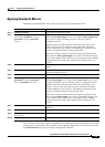
• If you are not using sequences and you have not assigned a profile to an LRE port, the port has a
default profile of LRE-10 or LRE-6 (see
Table 12-1 and Table 12-2). Port profiles have priority over
global profiles. If you assign a global profile to the switch, the switch uses the global profile except
on any LRE ports on which a specific profile was assigned.
When you assign a different profile to a switch LRE port, the port immediately resets and uses the
newly assigned profile.
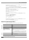
• Use the LL profiles (LRE-5LL, LRE-10LL, and LRE-15LL) on the Catalyst 2950ST-8 LRE and
2950ST-24 LRE switches with care. These profiles have the low-latency (LL) feature enabled and
the interleave feature disabled. The LL feature does not delay data transmission, but it makes data
more susceptible to interruptions on the LRE link.
All other profiles have the interleave feature enabled and the LL feature disabled. The interleave
feature provides maximum protection against small interruptions on the LRE link but delays data
transmission.
For information on configuring the interleaving delay on the LRE ports, see the “Configuring LRE
Interleave” section on page 12-19.
• The symmetric profiles (LRE-5, LRE-10, LRE-15, LRE-8, LRE-7, LRE-4, LRE-3, and LRE-2) on
the Catalyst 2950ST-8 LRE and the 2950ST-24 LRE switches provide full-duplex throughput on the
link between the LRE switch and CPE device. Under ideal conditions, this can mean up to 30
Mbps
of bandwidth on the LRE link if you are using the LRE-15 profile.
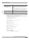
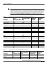
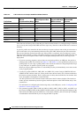
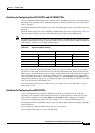
LRE-9-6 9.375 6.250 25 19
LRE-9-4 9.375 4.688 25 16
LRE-9-3 9.375 3.125 25 13
LRE-6 (default) 6.250 6.250 19 19
LRE-6-4 6.250 4.6888 19 16
LRE-6-3 6.250 3.125 19 13
LRE-4 4.688 4.688 16 16
LRE-4-3 4.688 3.125 16 13
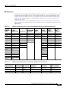
Table 12-2 LRE Profiles for the Catalyst 2950ST-24 LRE 997 Switches
Profile Name
LRE Link
Downstream Rate (Mbps)
LRE Link Upstream Rate
(Mbps)
Theoretical Minimum
SNR Downstream
Theoretical
Minimum SNR
Upstream