


12-20
Catalyst 2950 and Catalyst 2955 Switch Software Configuration Guide
OL-10101-02
Chapter 12 Configuring LRE
Configuring LRE Ports
A lower value of the interleave block size means less tolerance to noise and causes a lower latency of
frame transmission. For example, lower values of the interleave block size can be used for voice
applications. A higher value of the interleave block size means higher tolerance to noise and causes
higher latency in the frame transmission. For example, higher values of the interleave block size can be
used for data applications.
If a lower latency of frame transmission is required, you can use a lower interleave value, but the LRE
switch will have less tolerance to noise.
Follow these guidelines for configuring the interleave delay:
• Interleave delay is applicable only when the non-LL profiles are used. Existing LL profiles are
supported.
• Interleave block size values of 0, 1, 2, 8, or 16 are supported.
• Different ports with the same profile can have different interleave settings.
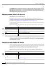
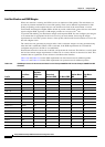
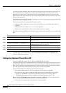
Beginning in privileged EXEC mode, follow these steps to set the interleave block size on a specific LRE
port:
To return the port to its default setting, use the no interleave downstream value upstream value
interface configuration command.
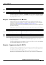
Configuring Upstream Power Back-Off
You can configure this feature only on a Catalyst 2950ST-24 LRE 997 switch.
The upstream power back-off mechanism allows for normalization of the upstream receive power levels
by requiring the CPE devices on shorter lines to send at a lower power level than the CPEs on longer
lines. You can change the upstream power back-off values by either selecting a standard noise model or
by setting an offset value for the default reference power spectral density (PSD).
Follow these guidelines for configuring upstream power back-off:
• The reference PSD number is based on an upstream carrier frequency of 4.8 MHz.
• You can use the offset values to adjust the CPE transmit reference PSD relative to the default
reference of –140 dBm/Hz. A zero value for the offset corresponds to a reference PSD of
–140 dBm/Hz. The smallest offset is 30 dBm/Hz, and the corresponding value is 300.
When you enter the lre upbo global configuration command, all LRE links are reset to the UP state.
Before configuring the reference TX power level, follow these guidelines:
• Verify how this command affects the network in a lab environment.
Command Purpose
Step 1
configure terminal Enter global configuration mode.
Step 2
interface interface-id Specify the LRE port to be configured, and enter interface
configuration mode.
Step 3
interleave downstream value upstream value Enter the downstream and upstream values. Supported values for
interleave block sizes are 0, 1, 2, 8, or 16.
Step 4
end Return to privileged EXEC mode.
Step 5
show controllers lre status interleave Verify the change.
Step 6
copy running-config startup-config (Optional) Save your entries in the configuration file.