


12-2
Catalyst 2950 and Catalyst 2955 Switch Software Configuration Guide
OL-10101-02
Chapter 12 Configuring LRE
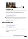
Understanding LRE Features
• LRE link—This is the connection between the switch LRE port and the RJ-11 wall port on an LRE
CPE device such as the Cisco
575 LRE CPE or the Cisco 585 LRE CPE. This connection can be
through categorized or noncategorized unshielded twisted-pair cable and can extend to distances of
up to 5000
feet (1524 meters).
• CPE Ethernet link—This is the connection between the CPE Ethernet port and an Ethernet device,
such as a PC. This connection is through standard Category 5 cabling and can extend to distances
of up to 328
feet (100 meters).
The actual line speed in either direction between an LRE switch port and a remote Ethernet device
depends on the LRE link speed and the CPE Ethernet link speed. For example, if a PC Ethernet port is
configured to 100
Mbps and the LRE port is configured with an upstream link speed of 5.69 Mbps, the
actual upload rate provided to the PC user is 5.69 Mbps, not 100 Mbps.
For LRE troubleshooting information, see the “Diagnosing LRE Connection Problems” section on
page 31-17. For more information about the LRE commands, see the command reference for this release.
LRE Links and LRE Profiles
The LRE link settings define the connection between the LRE switch port and the CPE RJ-11 wall port.
The LRE link provides symmetric and asymmetric bandwidth for data, voice, and video traffic.
Symmetric transmission occurs when the downstream and upstream bandwidths are the same.
Asymmetric transmission occurs when the downstream and the upstream bandwidths differ. Downstream
transmission refers to the traffic going from the LRE switch to the CPE device. Upstream transmission
refers to the traffic going from the CPE device to the LRE switch.
The switch controls upstream and downstream rates on the LRE link by using configurations called
profiles. Depending on the profile, the upstream and downstream bands on an LRE link can range from
approximately 1 to 18.750
Mbps.
This section discusses these topics:
• LRE Profiles, page 12-2
• LRE Sequences, page 12-5
• CPE Ethernet Links, page 12-6
LRE Profiles
When the LRE switch establishes a link with the CPE device, the switch downloads its profile settings
to the CPE device so that the switch and CPE device operate with the same configuration.
The LRE switches are shipped with system-defined profiles. You can configure a profile on a global or
per-port basis. By default, all LRE ports on the Catalyst 2950ST-8 LRE and 2950ST-24 LRE switches
are enabled with the LRE-10 profile, and all LRE ports on the Catalyst 2950ST-24 LRE 997 switches
are enabled with the LRE-6 profile. These default profile allows the upstream and downstream effective
data rate on the LRE link to be 10
Mbps and 6.0 Mbps, respectively.
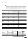
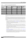
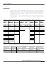
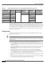
Table 12-1 and Table 12-2 contain the full list of LRE profiles, as well as their downstream and upstream
rates (in Mbps and their theoretical upstream and downstream signal-to-noise [SNR] rates in decibels
[dB]).
Note Consult the regulations for connecting to the public switched telephone network (PSTN) in your area.