


14-3
Catalyst 2950 and Catalyst 2955 Switch Software Configuration Guide
OL-10101-02
Chapter 14 Configuring MSTP
Understanding MSTP
All MST instances within the same region share the same protocol timers, but each MST instance
has its own topology parameters, such as root switch ID, root path cost, and so forth. By default, all
VLANs are assigned to the IST.
An MST instance is local to the region; for example, MST instance 1 in region A is independent of
MST instance 1 in region B, even if regions A and B are interconnected.
• A common and internal spanning tree (CIST), which is a collection of the ISTs in each MST region,
and the common spanning tree (CST) that interconnects the MST regions and single spanning trees.
The spanning tree computed in a region appears as a subtree in the CST that encompasses the entire
switched domain. The CIST is formed by the spanning-tree algorithm among switches that support
the IEEE 802.1w, IEEE 802.1s, and IEEE 802.1D standards. The CIST in a MST region is the same
as the CST outside a region.
For more information, see the “Operations Within an MST Region” section on page 14-3 and the
“Operations Between MST Regions” section on page 14-3.
Operations Within an MST Region
The IST connects all the MSTP switches in a region. When the IST converges, the root of the IST
becomes the IST master. It is the switch within the region with the lowest switch ID and path cost to the
CST root. The IST master also is the CST root if there is only one region in the network. If the CST root
is outside the region, one of the MSTP switches at the boundary of the region is selected as the IST
master.
When an MSTP switch initializes, it sends BPDUs claiming itself as the root of the CST and the IST
master, with both of the path costs to the CST root and to the IST master set to zero. The switch also
initializes all of its MST instances and claims to be the root for all of them. If the switch receives superior
MST root information (lower switch ID, lower path cost, and so forth) than stored for the switch, it
relinquishes its claim as the IST master.
During initialization, a region might have many subregions, each with its own IST master. As switches
receive superior IST information, they leave their old subregions and join the new subregion that
contains the true IST master. Thus all subregions shrink, except for the one that contains the true IST
master.
For correct operation, all switches in the MST region must agree on the same IST master. Therefore, any
two switches in the region synchronize their port roles for an MST instance only if they converge to a
common IST master.
Operations Between MST Regions
If there are multiple regions or legacy IEEE 802.1D switches within the network, MSTP establishes and
maintains the CST, which includes all MST regions and all legacy STP switches in the network. The
MST instances combine with the IST at the boundary of the region to become the CST.
The IST connects all the MSTP switches in the region and appears as a subtree in the CST that
encompasses the entire switched domain, with the root of the subtree being the IST master. The MST
region appears as a virtual switch to adjacent STP switches and MST regions.
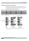
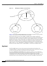
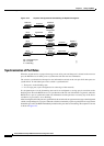
Figure 15-1 shows a network with three MST regions and a legacy IEEE 802.1D switch (D). The IST
master for region 1 (A) is also the CST root. The IST master for region 2 (B) and the IST master for
region 3 (C) are the roots for their respective subtrees within the CST. The RSTP runs in all regions.