


14-2
Catalyst 2950 and Catalyst 2955 Switch Software Configuration Guide
OL-10101-02
Chapter 14 Configuring MSTP
Understanding MSTP
Understanding MSTP
MSTP, which uses RSTP for rapid convergence, enables VLANs to be grouped into a spanning-tree
instance, with each instance having a spanning-tree topology independent of other spanning-tree
instances. This architecture provides multiple forwarding paths for data traffic, enables load balancing,
and reduces the number of spanning-tree instances required to support a large number of VLANs.
These sections describe how the MSTP works:
• Multiple Spanning-Tree Regions, page 14-2
• IST, CIST, and CST, page 14-2
• Hop Count, page 14-4
• Boundary Ports, page 14-5
• Interoperability with IEEE 802.1D STP, page 14-5
For configuration information, see the “Configuring MSTP Features” section on page 14-11.
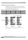
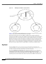
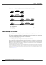
Multiple Spanning-Tree Regions
For switches to participate in multiple spanning-tree (MST) instances, you must consistently configure
the switches with the same MST configuration information. A collection of interconnected switches that
have the same MST configuration comprises an MST region as shown in
Figure 14-1 on page 14-4.
The MST configuration determines to which MST region each switch belongs. The configuration
includes the name of the region, the revision number, and the MST VLAN-to-instance assignment map.
You configure the switch for a region by using the spanning-tree mst configuration global
configuration command, after which the switch enters the MST configuration mode. From this mode,
you can map VLANs to an MST instance by using the instance MST configuration command, specify
the region name by using the name MST configuration command, and set the revision number by using
the revision MST configuration command.
A region can have one or multiple members with the same MST configuration; each member must be
capable of processing RSTP bridge protocol data units (BPDUs). There is no limit to the number of MST
regions in a network, but each region can only support up to 16spanning-tree instances. Instances can be
identified by any number in the range from 0 to15You can assign a VLAN to only one spanning-tree
instance at a time.
IST, CIST, and CST
Unlike PVST+ and rapid PVST+ in which all the spanning-tree instances are independent, the MSTP
establishes and maintains two types of spanning trees:
• An internal spanning tree (IST), which is the spanning tree that runs in an MST region.
Within each MST region, the MSTP maintains multiple spanning-tree instances. Instance 0 is a
special instance for a region, known as the internal spanning tree (IST). All other MST instances are
numbered from 1 to 15.
The IST is the only spanning-tree instance that sends and receives BPDUs. All of the other
spanning-tree instance information is contained in M-records, which are encapsulated within MSTP
BPDUs. Because the MSTP BPDU carries information for all instances, the number of BPDUs that
need to be processed to support multiple spanning-tree instances is significantly reduced.