


1-18
Catalyst 2950 and Catalyst 2955 Switch Software Configuration Guide
OL-10101-02
Chapter 1 Overview
Network Configuration Examples
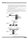
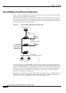
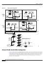
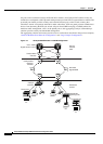
Figure 1-4 Network Hotel Configuration
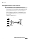
Service-Provider Central-Office Configuration
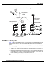
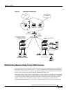
Figure 1-5 shows the Catalyst 2950ST-24 LRE 997 switches in a service-provider central-office network
environment. The Catalyst 2950ST-24 LRE 997 switches have DC-input power supply and are compliant
with the VDSL 997 band plan. The Catalyst 2950 LRE switches are located in a central office and are
connected to the Cisco 576 LRE 997 CPE devices located in different buildings. The switches also
connect to a Cisco 7500 router.
Cisco 575
LRE CPE
PSTN
PBX
Floor 3
Floor 4
Rooms
and
users
Rooms
and
users
Cisco
LRE 48
POTS
splitters
Cisco 2600 router
Servers
Catalyst 2950ST-8 LRE and
2950ST-24 LRE switches
Catalyst 2950 or
Catalyst 3550 switch
Patch panel
89514
POTS telephones
Laptop
Cisco 575
LRE CPE
Laptop
POTS telephones
Required
microfilter
Required
microfilter
Required
microfilter
Cisco 585
LRE CPE
IP
phone
Laptop
Environmental
controls
Required
microfilter
Set-top
box
TV
IP
POTS telephone
POTS telephone
Cisco 585
LRE CPE
IP
phone
Laptop
Environmental
controls
Set-top
box
TV
IP