


3-2
Catalyst 2950 and Catalyst 2955 Switch Software Configuration Guide
OL-10101-02
Chapter 3 Configuring Catalyst 2955 Switch Alarms
Understanding Catalyst 2955 Switch Alarms
Global Status Monitoring Alarms
The Catalyst 2955 switch contains facilities for processing alarms related to temperature and power
supply conditions. These are referred to as global or facility alarms.
Table 3-1 lists the three global
alarms and their descriptions and functions.
FCS Error Hysteresis Threshold
The Ethernet standard calls for a maximum bit error rate of 10
-8
. In the Catalyst 2955 switch, the bit error
rate configurable range is from 10
-6
to 10
-11
. The bit error rate input to the switch is a positive exponent.
If you want to configure the bit error rate of 10
-9
, then you enter the value 9 for the exponent. By default,
the FCS bit error rate is 10
-8
.
You can set the FCS error hysteresis threshold to prevent the toggle of the alarm when the actual bit error
rate fluctuates near the configured bit error rate. The hysteresis threshold is defined as the ratio between
the alarm clear threshold to the alarm set threshold, expressed as a percentage value.
For example, if the FCS bit error rate alarm value is configured to 10
–8
, that value is the alarm set
threshold. To set the alarm clear threshold at 5*10
-10
, the hysteresis, value h, is determined as follows:
h = alarm clear threshold / alarm set threshold
h = 5*10
-10
/ 10
-8
= 5*10
-2
= 0.05 = 5 percent
The FCS hysteresis threshold is applied to all ports on the Catalyst 2955 switch. The allowable range is
from 1 to 10 percent. The default value is 10 percent. See the
“Configuring the FCS Bit Error Rate
Alarm” section on page 3-7 for more information.
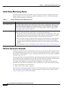
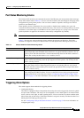
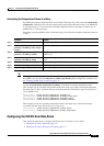
Ta b l e 3-1 Catalyst 2955 Global Status Monitoring Alarms
Alarm Description
Power Supply Alarm The switch monitors dual DC power supply levels. If the system is configured to operate in a dual
power mode, an alarm triggers if a power supply fails or is missing. The alarm is automatically
cleared when both power supplies are present or working. You can configure the power supply
alarm to be connected to the hardware relays. For more information, see the
“Configuring the
Power Supply Alarm” section on page 3-5.
Temperature Alarms The switch contains a temperature sensor that monitors the environmental conditions inside the
switch. The switch contains two alarms that are associated with temperature.
• The primary alarm is enabled automatically to trigger both at a low temperature (-20
o
C) and a
high temperature (95
o
C) for the safe operation of the switch. It cannot be changed or disabled.
By default, the primary temperature alarm is associated with the major relay.
• You can use the secondary temperature alarm to trigger an alarm when the system temperature
is greater than the configured temperature threshold. The lower threshold is configurable
within the range of 40
o
C to the maximum threshold, 95
o
C. The secondary alarm is disabled by
default.
For more information, see the “Configuring the Switch Temperature Alarms” section on page 3-6.