


28-5
Catalyst 2950 and Catalyst 2955 Switch Software Configuration Guide
OL-10101-02
Chapter 28 Configuring Network Security with ACLs
Understanding ACLs
–
UDP (You can specify a UDP source, destination port number, or both at the same time.)
Note A mask can be a combination of either multiple Layer 3 and Layer 4 fields or of multiple Layer 2 fields.
Layer 2 fields cannot be combined with Layer 3 or Layer 4 fields.
There are two types of masks:
• User-defined mask—masks that are defined by the user.
• System-defined mask—these masks can be configured on any interface:
Switch (config-ext-nacl)# permit tcp any any
Switch (config-ext-nacl)# deny tcp any any
Switch (config-ext-nacl)# permit udp any any
Switch (config-ext-nacl)# deny udp any any
Switch (config-ext-nacl)# permit ip any any
Switch (config-ext-nacl)# deny ip any any
Switch (config-ext-nacl)# deny any any
Switch (config-ext-nacl)# permit any any
Note In an IP extended ACL (both named and numbered), a Layer 4 system-defined mask cannot
precede a Layer 3 user-defined mask. For example, a Layer 4 system-defined mask such as
permit tcp any any or deny udp any any cannot precede a Layer 3 user-defined mask such as
permit ip 10.1.1.1 any. If you configure this combination, the ACL is not allowed on a Layer 2
interface. All other combinations of system-defined and user-defined masks are allowed in
security ACLs.
The switch ACL configuration is consistent with other Cisco Catalyst switches. However, there are
significant restrictions for configuring ACLs on the switches.
Only four user-defined masks can be defined for the entire system. These can be used for either security
or quality of service (QoS) but cannot be shared by QoS and security. You can configure as many ACLs
as you require. However, a system error message appears if ACLs with more than four different masks
are applied to interfaces. For more information about error messages, see the system message guide for
this release.
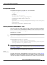
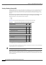
Table 28-1 lists a summary of the ACL restrictions on the switches.
Guidelines for Applying ACLs to Physical Interfaces
When applying ACLs to physical interfaces, follow these configuration guidelines:
• Only one ACL with these limitations can be attached to an interface:
–
Gigabit Ethernet ports support up to 100 ACEs per 1 ACL per port.
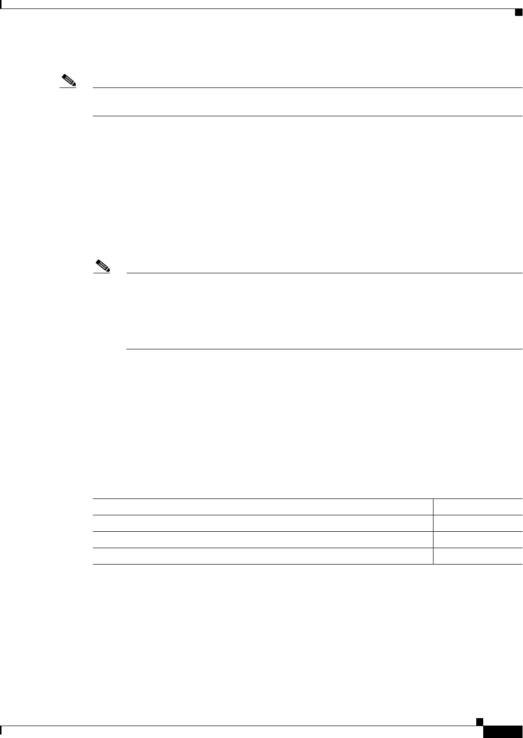
Ta b l e 28-1 Summary of ACL Restrictions
Restriction Number
Number of user-defined masks allowed in an ACL 1
Number of ACLs allowed on an interface 1
Total number of user-defined masks for security and QoS allowed on a switch 4