


13-22
Catalyst 2950 and Catalyst 2955 Switch Software Configuration Guide
OL-10101-02
Chapter 13 Configuring STP
Configuring Spanning-Tree Features
Configuring Spanning Tree for Use in a Cascaded Stack
Spanning tree uses default values that can be reduced when configuring your switch in cascaded
configurations. If a root switch is part of a cluster that is one switch from a cascaded stack, you can
customize spanning tree to reconverge more quickly after a switch failure.
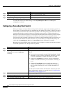
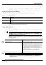
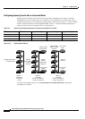
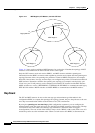
Figure 13-4 shows switches
in three cascaded stacks that use the GigaStack GBIC. Table 13-5 shows the default spanning-tree
settings and those that are acceptable for these configurations.
Figure 13-4 Gigabit Ethernet Stack
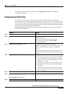
To return to the default setting, use the no spanning-tree transmit hold-count value global
configuration command.
Ta b l e 13-5 Default and Acceptable Spanning-Tree Parameter Settings (in seconds)
STP Parameter STP Default Acceptable for Option 1 Acceptable for Option 2 Acceptable for Option 3
Hello Time 2 1 1 1
Max Age 20 6 10 6
Forwarding Delay 15 4 7 4
Catalyst 2950, 2955,
or 3550 switches
74621
Catalyst
2950, 2955,
or 3550
switches
Catalyst
3550 or
6000 series
backbone
Option 1:
standalone
cascaded
cluster
Option 2:
cascaded
cluster connected to
a Layer 2 backbone
Option 3:
cascaded
cluster connected to
a Layer 3 backbone
Catalyst 3550
series switch
Catalyst 6000
switch
Layer 3
backbone
Cisco 7000
router
Catalyst 2950,
2955, or 3550
switches
Cisco 7000
router