


3-5
Cisco BPX 8600 Series Installation and Configuration
Release 9.3.10, Part Number 78-11603-01 Rev. D0, July 2001
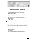
Chapter 3 BPX Switch Common Core Components
Broadband Controller Card (BCCs)
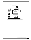
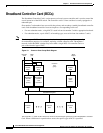
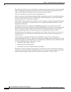
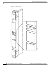
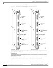
Figure 3-2 BCC4V Block Diagram
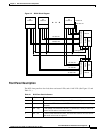
Front Panel Description
The BCC front panel has four Led, three card status LEDs, and a LAN LED. (See Figure 3-3 and
Table 3-1.)
S
s6392
BCC-A
Arbiter
SIU
TX data-2A
RX data-2A
TX data-12A
RX data-12A
TX data-1B
RX data-1B
RX data-2B
TX data-2B
TX data-12B
RX data-12B
Polling bus-A
Polling bus-B
TX data-1A
RX data-1A
I/O
module 1
DRSIU
I/O
module 2
DRSIU
I/O
module 12
DRSIU
BCC-A
16 x 32 Xpoint switch 16 x 32 Xpoint switch
Arbiter
SIU
S6393
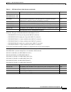
Table 3-1 BCC Front Panel Indicators
Number Indicator Function
1 LAN Indicates there is data activity over the Ethernet LAN port.
2 card - act Card active LED indicates this BCC is online and actively controlling
the node.
3 card - stby Card standby LED indicates this BCC is offline but is ready to take over
control of the node at a moments notice.
4 card - fail Card fail LED indicates this BCC has failed the internal self-test routine
and needs to be reset or replaced.