


13-13
Cisco BPX 8600 Series Installation and Configuration
Release 9.3.10, Part Number 78-11603-01 Rev. D0, July 2001
Chapter 13 Installing the BPX Switch Cards
Installation of APS Redundant Frame Assembly and Backcards
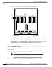
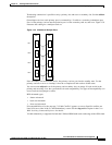
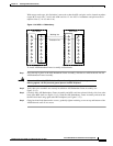
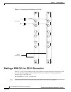
With current card cages, this limitation is removed so that the APS card pairs can be located anywhere
except BCC cards slots 7 and 8, and ASM card slot 15. An APS 1+1 redundant card pair must be in
adjacent slots (2,3 or 4,5 and so on).
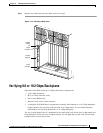
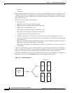
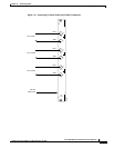
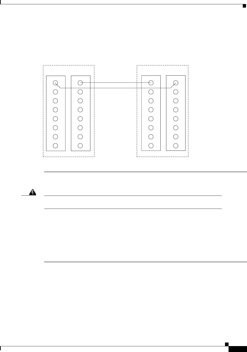
Figure 13-10 APS 1+1 Redundancy
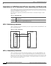
To install APS Redundant Frame Assembly and backcards:
Step 1 If not already in place in the APS Redundant Frame Assembly, slide the two APS backcards into the
APS Redundant Frame Assembly.
Warning
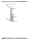
Nylon standoffs on the APS Redundant Frame Assembly must be in place to prevent
shorting against -48 VDC pins and ground pins on the BPX Midplane.
Step 2 Verify that nylon standoffs are securely installed on APS Redundant Frame Assembly (see
Figure 13-11).
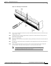
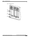
Step 3 Carefully slide APS Redundancy Frame Assembly and APS cards into selected side-by-side slots at the
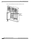
back of the BPX shelf (see Figure 13-12). Slide the APS Redundancy Frame Assembly and cards into
the BPX shelf until snug against the BPX midplane (see Figure 13-13).
Step 4 Goingbackandforthbetweenthescrews,graduallytightenretainingscrewsattopandbottomofthe
APS backcards until all are secure.
Working line
Protection line
17722
BPX switch
BPX switch