23-2
Cisco BPX 8600 Series Installation and Configuration
Release 9.3.10, Part Number 78-11603-01 Rev. D0, July 2001
Chapter 23 Configuring BXM Virtual Switch Interface
Virtual Switch Interface
When a VSI is activated on a port, trunk, or virtual trunk so that it can be used by a master controller,
such as an SES PNNI or an MPLS controller, the resources of the virtual interface associated with the
port, trunk, or virtual trunk are made available to the VSI. These control planes can be external or
internal to the switch. The VSI provides a mechanism for networking applications to control the switch
and use a partition of the switch resources.
VSI on the BPX provides:
• Class of Service templates
• Virtual trunk support for VSI
• Support for VSI master redundancy
• Multiple VSI partitions
• Soft and Dynamic Partitioning
• SV+ support for VSI
Multiple Partitioning
VSI was implemented first on the BPX 8650 in Release 9.1, which uses VSI to perform Multiprotocol
Label Switching and allowed support for VSI on BXM cards and for partitioning BXM resources
between Automatic Routing Management and a VSI MPLS controller. BPX software uses a partition to
identify and assign resources such as LCNs, VPIs, and bandwidth to a controller. Multiple VSI
partitions may be defined on a single physical port.
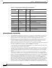
BPX Release 9.2 supports up to three VSI partitions in addition to Automatic Routing Management. The
VSI partitions are controlled by VSI Masters such as the PNNI or MPLS controllers. When configuring,
allocate switch resources to Automatic Routing Management and VSI slaves. Resources allocated to
Automatic Routing Management and then reallocated to VSI.
Release 9.3.10 introduces Soft Partitioning and Dynamic Partitioning in order to support the smooth
introduction of another VSI controller into a BPX network already configured with an existing VSI
controller, easier tuning of switch resources, and the migration of Automatic Routing Management to PNNI
(see the section Soft and Dynamic Partitioning later in this chapter).
Multiprotocol Label Switching
Multiprotocol Label Switching (MPLS, previously called Tag Switching) enables routers at the edge of a
network to apply simple labels to packets (frames), allowing devices in the network core to switch packets
according to these labels with minimal lookup activity. MPLS in the network core can be performed by
switches, such as ATM switches, or by existing routers.
MPLS integrates virtual circuit switching with IP routing to offer scalable IP networks over ATM. MPLS
support data, voice, and multimedia service over ATM networks. MPLS summarizes routing decisions so
that switches can perform IP forwarding, as well as bringing other benefits that apply even when MPLS is
used in router-only networks.
Using MPLS techniques, it is possible to set up explicit routes for data flows that are constrained by
path, resource availability, and requested Quality of Service (QoS). MPLS also facilitates highly
scalable Virtual Private Networks.
MPLS assigns labels to IP flows, placing them in the IP frames. The frames can then be transported
across packet or cell-based networks and switched on the labels rather than being routed using IP
address look-up.


