


2-5
Cisco BPX 8600 Series Installation and Configuration
Release 9.3.10, Part Number 78-11603-01 Rev. D0, July 2001
Chapter 2 BPX Switch Physical Overview
Card Shelf Configuration
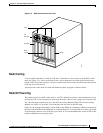
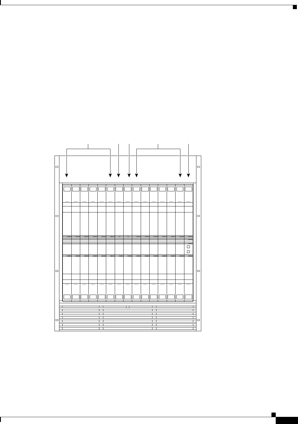
Card Shelf Configuration
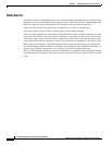
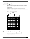
There are fifteen vertical slots in the front of the BPX switch enclosure to hold plug-in cards (see
Figure 2-5).
The middle two slots, slots number 7 and number 8, are used for the primary and secondary Broadband
Controller Cards (BCC).
The right-most slot, number 15, is used to hold the single Alarm/Status Monitor Card.
The other twelve slots, number 1 through number 6 and number 8 through number 14, can be used for
the Network Interface and Service Interface cards.
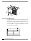
Figure 2-5 BPX Switch Card Shelf Front View
BPX Switch Major Hardware Component Groups
There are four major groups of hardware components in the BPX switch:
• Common Core Components
• Network Interface Components
1234567
BCC-A
8
BCC-B
9 101112131415
ASM
status
port
13
act failstby
card
BNI-3/T3
81234
status
port
13
act failstby
card
BNI-3/T3
81234
status
port
13
act failstby
card
BNI-3/T3
81234
status
port
13
act failstby
card
BNI-3/T3
81234
status
port
13
act failstby
card
BNI-3/T3
81234
status
port
13
act failstby
card
BNI-3/T3
81234
LAN
BCC-15
81236
LAN
BCC-15
81236
status
port
13
act failstby
card
BNI-3/T3
81234
status
port
13
act failstby
card
BNI-3/T3
81234
status
port
13
act failstby
card
BNI-3/T3
81234
status
port
13
act failstby
card
BNI-3/T3
81234
status
port
13
act failstby
card
BNI-3/T3
81234
status
port
13
act failstby
card
BNI-3/T3
81234
status
alarms
DC ok
major minor
AB
ACO hist
ACO
history clear
act failstby
card
ASM
81237
H8020
act failstby
card
act failstby
card
22222222222
BNI-3/T3
81234
2
General
purpose
card slots
BCC/
PRI
BCC/
SEC
ASM
General
purpose
card slots