


23-13
Cisco BPX 8600 Series Installation and Configuration
Release 9.3.10, Part Number 78-11603-01 Rev. D0, July 2001
Chapter 23 Configuring BXM Virtual Switch Interface
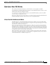
Overview: How VSI Works
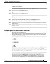
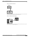
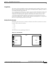
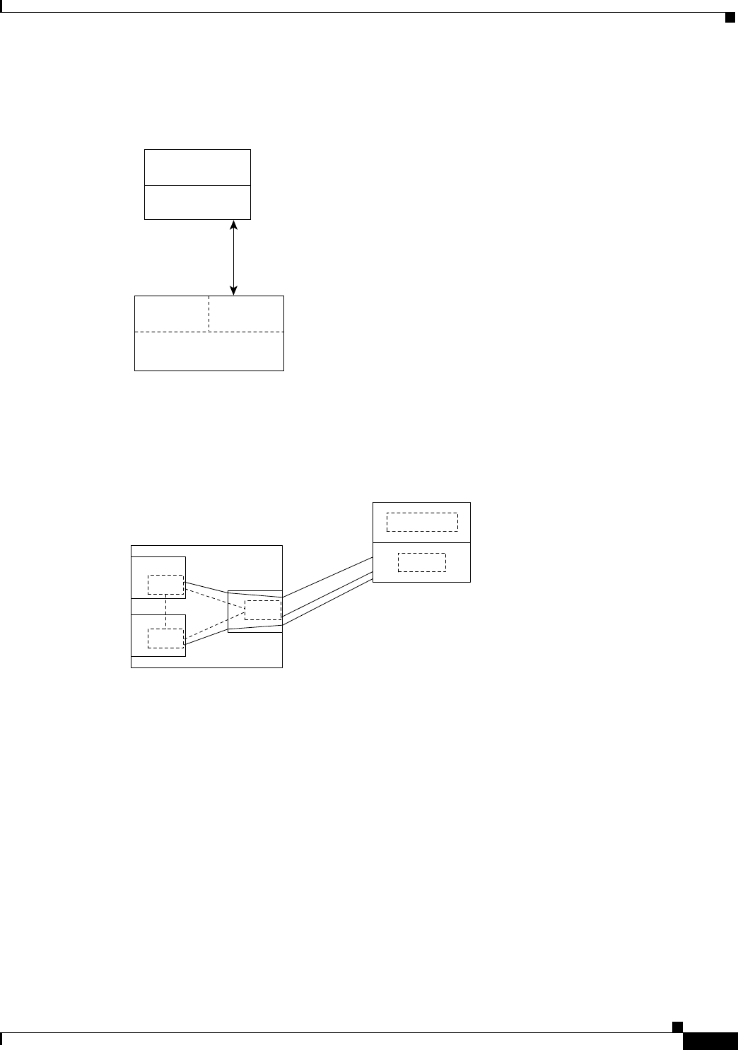
Figure 23-2 VSI, Controller and Slave VSI
The controller establishes a link between the VSI master and every VSI slave on the associated switch.
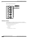
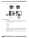
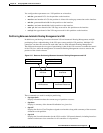
The slaves in turn establish links between each other (see Figure 23-3).
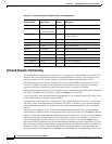
Figure 23-3 VSI Master and VSI Slave Example
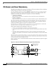
With a number of switches connected together, there are links between switches with cross-connects
established within the switch as shown in Figure 23-4.
VSI controller
(Tag, PNNI, etc.)
VSI master
BPX
17715
7000 series
router
VSI slaves
AutoRoute
Resource
management
Application
Master
MPLS controller
Switch
Slave
Slave
Slave
17713