


CHAPTER
9-1
Cisco BPX 8600 Series Installation and Configuration
Release 9.3.10, Part Number 78-11603-01 Rev. D0, July 2001
9
Installation in Customer Cabinet
This chapter provides installation steps for the mechanical placement of a BPX switch shelf in a
standard 19-inch customer-supplied equipment cabinet or rack with a rear rail setback at 30 inches.
Before proceeding to this chapter, complete the procedures in:
• Chapter 7, Preliminary Steps Before Installing
Installing a BPX Switch, Rear Rail Setback at 30-Inch
This procedure applies to a BPX switch shelf to be installed in a customer-supplied cabinet with rear
vertical rails located at a setback of approximately 30 inches from the front.
If the BPX switch shelf is DC powered, the DC Power Entry Modules are factory-installed in the lower
portion of the rear of the BPX switch shelf itself. Locate the DC Power Entry Module(s) and make sure
it/they are equipped as ordered.
If the BPX switch shelf is AC powered, you will also need to install an AC Power Assembly below it.
Preliminary Procedure
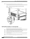
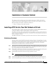
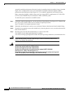
Proceed as follows to install the BPX switch shelf, referring to Figure 9-1 through Figure 9-3, and to
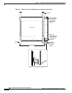
either Figure 9-4 for DC-powered systems or Figure 9-5 for AC-powered systems. Figure 9-2 shows the
location of the rear-located third rails in a customer supplied cabinet and of the corresponding
adjustable plates and support brackets on the BPX switch shelf.
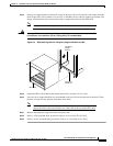
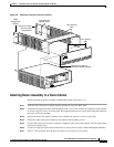
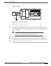
Step 1 With one person on each side of the BPX switch shelf, slide the BPX from lifting device and rest it on
the temporary space bar and temporary support brackets. positioning the slots at the rear of the pallet
tray over the locating tabs on the spacer bracket (see Figure 9-1).
Step 2 Slide the BPX switch shelf into the cabinet over the temporary support bar and brackets and into place
over the flanges of the brackets previously attached to the rear rails of the cabinet.
Step 3 SecuretheBPXswitchshelftothefrontrailusing8each#10-32screws.
Note European installations may use a size M6 metric screw.
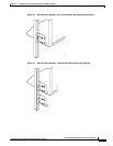
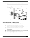
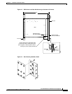
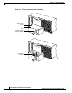
Step 4 Locate the rear support brackets (P/N 215960-00B and 215960-01B) in the miscellaneous parts kit.
Step 5 Position the adjustable plates with the tabs in the three punchouts facing up as shown in Figure 9-3.