


1-14
Cisco BPX 8600 Series Installation and Configuration
Release 9.3.10, Part Number 78-11603-01 Rev. D0, July 2001
Chapter 1 The BPX Switch: Functional Overview
BPX Switch Operation
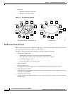
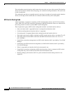
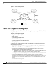
The routing hubs route the interface shelf connections across the core layer of the network.The interface
shelves do not need to maintain network topology nor connection routing information. This task is left
to their routing hubs.
This architecture provides an expanded network consisting of a number of nonrouting nodes (interface
shelves) at the edge of the network that are connected to the network by their routing hubs.
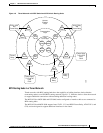
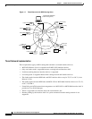
BPX Switch Routing Hubs
T1/E1 Frame Relay connections originating at IGX switch interface shelves and T1/E1 Frame Relay,
T1/E1 ATM, CES, and FUNI connections originating at MGX 8220 interface shelves are routed across
the routing network via their associated BPX switch routing hubs.
These requirements apply to BPX switch routing hubs and their associated interface shelves:
• Only one feeder trunk is supported between a routing hub and interface shelf.
• No direct trunking between interface shelves is supported.
• No routing trunk is supported between the routing network and interface shelves.
• The feeder trunks between BPX switch hubs and IGX switch interface shelves are either T3 or E3.
• The feeder trunks between BPX switch hubs and MGX 8220 interface shelves are T3, E3, or
OC-3-C/STM-1.
• Frame Relay connection management to an IGX switch interface shelf is provided by Cisco WAN
Manager.
• Frame Relay and ATM connection management to an MGX 8220 interface shelf is provided by
Cisco WAN Manager.
• Telnet is supported to an interface shelf; the vt command is not.
• Frame Relay connections originating at IGX switch interfaces shelves connected to IGX switch
routing hubs may also be routed across BPX switch intermediate nodes.
• Remote printing by the interface shelf via a print command from the routing network is not
supported.