


29-7
Cisco BPX 8600 Series Installation and Configuration
Release 9.3.10, Part Number 78-11603-01 Rev. D0, July 2001
Chapter 29 Replacing Parts
Replacing an AC Power Supply
Replacing an AC Power Supply
BPX switches are powered by redundant power supplies; either power supply can supply the current
requirements of the node. The AC Power Supply is part of an assembly which is replaced as a single
unit. Access to the AC Power Supply assembly is from the front, but first, the Air Intake Grille must be
removed.
To remove a power supply:
Step 1 If you haven’t already done so, check the status and output voltage of the power supplies at the node
using the dspasm command. Note which power supply is failed, A or B. Power supply A is on the right
side facing the rear of the node.
Step 2 Remove the Air Intake Grille. Locate the small access hole in the top, center of the Air Intake Grille.
Step 3 Fully insert a flat-bladed screwdriver (with a 1/4 in. blade) in the access hole.
Step 4 Rotate the screwdriver to release the spring latch holding the Air Intake Grille
(see Figure 29-4). The grille should pop out.
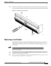
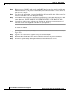
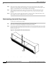
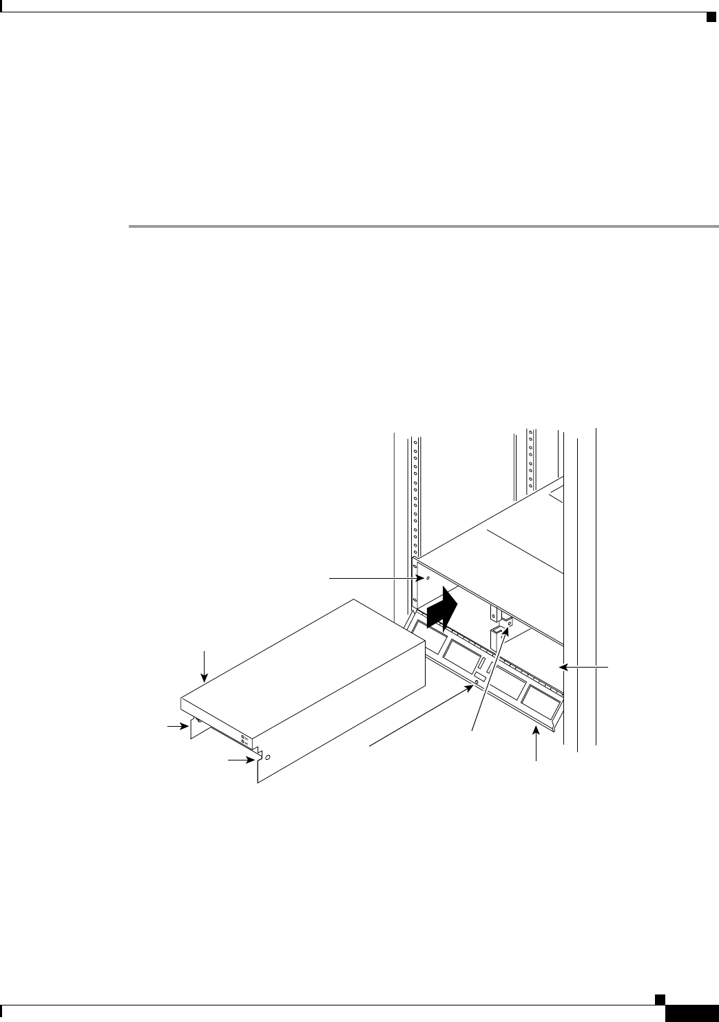
Figure 29-4 AC Power Supply Assembly
Step 5
Tilt the grille forward approximately a 45° angle, then lift if out and set it aside. This exposes the power
supply retainer bracket.
Step 6 With a flat-bladed screwdriver, loosen the retainer bracket hold-down screw in the center of the bracket
and tilt the bracket.
Step 7 Identify which power supply needs replacement. Power supply A is the unit on the left, B is on the right.
In most cases, the failed unit will be identified by a front panel lamp indication.
SLOT A
SLOT B
Power supply
thumb screw
Power supply
retainer
Retainer
captive
screw
H8212
Slot B empty if
non-redundant
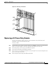
Power
supply
Power supply
plunger hole
Plunger
Power supply
thumb screw