


11-4
Cisco BPX 8600 Series Installation and Configuration
Release 9.3.10, Part Number 78-11603-01 Rev. D0, July 2001
Chapter 11 Installing the AC Shelf
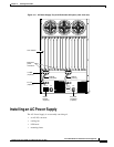
Installing an AC Power Supply Tray
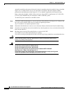
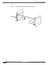
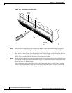
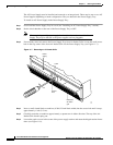
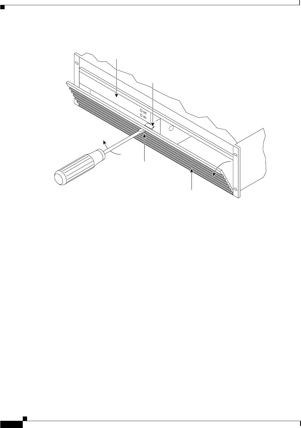
Figure 11-3 Removing an Air Intake Grille
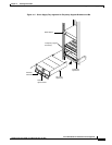
Step 6
Slide the Power Supply Tray in the rack between the BPX switch shelf and the temporary support
brackets and spacer bar (see Figure 11-2). If cables are attached, take care to avoid damaging them.
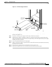
Step 7 Install screws and washers to loosely secure power supply assembly to the front of the BPX switch
shelf. Align the front flanges of the Power Supply Tray with the flanges on the BPX switch shelf and
tighten screws. Allow approximately 1/16” clearance between the BPX switch shelf and the Power
Supply Tray to provide sufficient clearance for inserting power supplies.
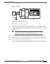
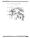
Step 8 Secure the Power Supply Tray to the rear support bracket (plate) using one #10-32 screw and flat washer
on each side. Use the lower hole in the brackets. Figure 11-4 shows the setup for a configuration with
the vertical rails at a 30 inch setback.
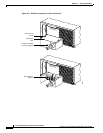
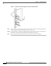
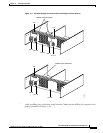
For a configuration with vertical rails at a 19.86 inch rail setback, attach one #10-32 screw and flat
washer to the single bracket on each side. Use the lower hole in the brackets. Figure 11-5 shows the
bracket configuration only; the power supply tray position is the same as shown for in Figure 11-4.
Latch
Access
hole
Released
air intake
grill
H7997
Power
supply