


22-10
Cisco BPX 8600 Series Installation and Configuration
Release 9.3.10, Part Number 78-11603-01 Rev. D0, July 2001
Chapter 22 Configuring Frame Relay to ATM Network and Service Interworking
BTM Control Mapping: Frames and Cells
BTM Control Mapping: Frames and Cells
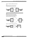
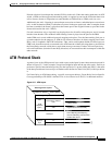
In addition to performing DLCI to PVC/VCC conversion, the network interworking feature provided
by the BTM in the IGX switch maps cell loss priority, congestion information, and management
information between Frame Relay and ATM formats as follows:
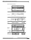
Cell Loss Priority, Frame Relay to ATM Direction
Each Frame Relay to ATM network interworking connection can be configured as one of the DE to CLP
mapping choices:
• The DE bit in the Frame Relay frame is mapped to the CLP bit of every ATM cell generated by the
segmentation process.
These 2 choices are not available on IGX switch NIW (network interworking):
• CLP is always 0.
• CLP is always 1.
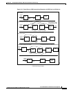
Cell Loss Priority, ATM to Frame Relay Direction
Each Frame Relay to ATM network interworking connection can be configured as one of the CLP to
DE mapping choices:
• If one or more ATM cells belonging to a frame has its CLP field set, the DE field of the Frame Relay
frame will be set.
This choice is not available:
• Choosing no mapping from CLP to DE.
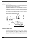
Congestion Indication, Frame Relay to ATM direction
• EFCI is always set to 0.
Congestion Indication, ATM to Frame Relay Direction
• If the EFCI field in the last ATM cell of a segmented frame is set, then FECN of the Frame Relay
frame will be set.
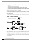
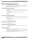
For PVC Status Management
The AIT/BTM does convert OAM cells to OAM fastpackets, and vice-versa, including the AIS OAM.
Also, “Abit” status is now propagated via software messaging.
The ATM layer and Frame Relay PVC Status Management can operate independently. The PVC status
from the ATM layer will be used when determining the status of the FR PVCs. However, no direct
actions of mapping LMI Abit to OAM AIS will be performed.