


11-6
Cisco BPX 8600 Series Installation and Configuration
Release 9.3.10, Part Number 78-11603-01 Rev. D0, July 2001
Chapter 11 Installing the AC Shelf
Installing an AC Power Supply Tray
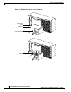
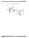
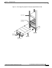
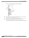
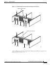
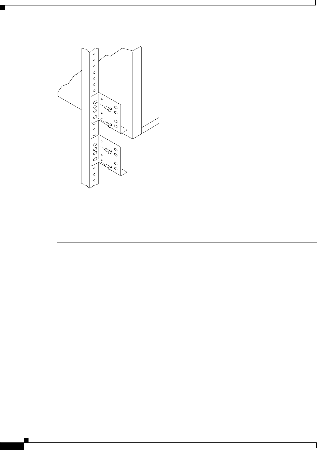
Figure 11-5 Securing an AC Power Supply Tray, 19.86 inch Rear Rail Setback
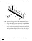
Step 9
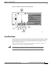
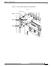
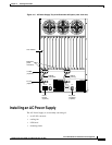
Connect and secure a power supply interconnect cable (Cable A in Figure 11-6) between the primary
AC Power Supply and the BPX switch backplane power connector.
Step 10 Connect and secure a second power supply interconnect cable (Cable B in Figure 11-6) between the
redundant AC Power Supply and the BPX switch backplane power connector.
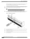
Step 11 Remove the temporary support bracket and spacer bracket from the front of the cabinet
14173