


1-44
Cisco BPX 8600 Series Installation and Configuration
Release 9.3.10, Part Number 78-11603-01 Rev. D0, July 2001
Chapter 1 The BPX Switch: Functional Overview
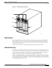
Switch Availability
Node Alarms
Each BPX switch shelf within the network runs continuous background diagnostics to verify the proper
operation of all active and standby cards, backplane control, data, and clock lines, cabinet temperature,
and power supplies. These background tests are transparent to normal network operation.
Each card in the node has front-panel LEDs to indicate active, failed, or standby status.
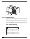
Each power supply has green LEDs to indicate proper voltage input and output.
An Alarm, Status, and Monitor card collects all the node hardware status conditions and reports it using
front panel LED indicators and alarm closures. Indicators are provided for major alarm, minor alarm,
ACO, power supply status, and alarm history. Alarm relay contact closures for major and minor alarms
are available from each node through a 15-pin D-type connector for forwarding to a site alarm system.
BPX switches are completely compatible with the network status and alarm display provided by the
Cisco WAN Manager NMS workstation. In addition to providing network management capabilities, it
displays major and minor alarm status on its topology screen for all nodes in a network.
The Cisco WAN Manager NMS also provides a maintenance log capability with configurable filtering
of the maintenance log output by node name, start time, end time, alarm type, and user-specified search
string.