


29-5
Cisco BPX 8600 Series Installation and Configuration
Release 9.3.10, Part Number 78-11603-01 Rev. D0, July 2001
Chapter 29 Replacing Parts
Replacing a DC Power Entry Module
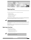
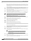
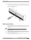
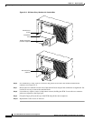
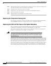
Figure 29-2 Removing a Line Module
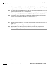
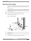
Replacing a DC Power Entry Module
DC Power Entry Modules (PEMs) contain few active components so they should rarely need
replacement. Access is from the back of the node.
To remove a PEM:
Step 1 Check the node system voltage by using the Display Power (dsppwr) command. Note which input has
failed, A or B. Power Supply A is the unit on the right side facing the rear of the node.
Step 2 Turn off the primary source of power to the PEM to be replaced.
Step 3 Turn off the circuit breaker on the PEM to be replaced.
Step 4 Remove the two screws holding the conduit box cover (see Figure 29-3). Or, remove the plastic cover
plate over the input terminal block.
Step 5 Remove the power input wiring at the PEM terminal block.
14 13 12 11 10
7
BCC-A
8
BCC-B
6
9
15
ASM
LM–
3/T3
LM–
3/T3
LM–
3/T3
LM–
3/T3
LM–
3/T3
LM–
3/T3
LM–
3/T3
LM–
3/T3
LM–
3/T3
LM–
3/T3
LM–
3/T3
LM–
3/T3
LM–
3/T3
5432
1
LM–
3/T3
LM–
3/T3
PORT 2
R
X
T
X
PORT 3
R
X
T
X
PORT 1
R
X
T
X
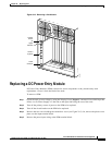
LM-3T3
(Typical)
Upper
extractor
Lower
extractor
Captive
screws
(2)
H8001