


11-12
Cisco BPX 8600 Series Installation and Configuration
Release 9.3.10, Part Number 78-11603-01 Rev. D0, July 2001
Chapter 11 Installing the AC Shelf
Card Slot Fuses
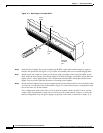
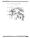
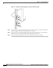
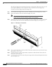
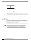
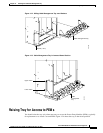
Figure 11-10 AC Power
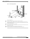
Step 5
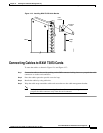
As applicable, provide a convenience AC outlet strip, with at least four outlets, near the BPX switch to
power optional modems, CSU, or DSUs, test equipment, and so on. There is no accessory AC outlet
supplied on the BPX switch. This outlet strip should be connected to a source of AC voltage normal for
the region (such as, 115 VAC for domestic US use).
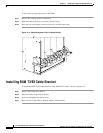
Step 6 Proceed to Chapter 13, Installing the BPX Switch Cards.
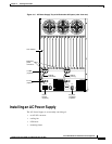
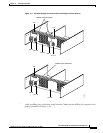
Card Slot Fuses
Fuses for each card slot on the backplane of the BPX switch protect against catastrophic backplane
damage in the event of a shorted connector power pin. The card slot fuses are designated F4 through
F18, corresponding to card slot numbers 1 through 15, respectively.
Backplane fuses should rarely, if ever, need replacement.
See Chapter 29, Replacing Parts, for instructions on replacement of these fuses, and contact Customer
Service for assistance regarding their replacement.
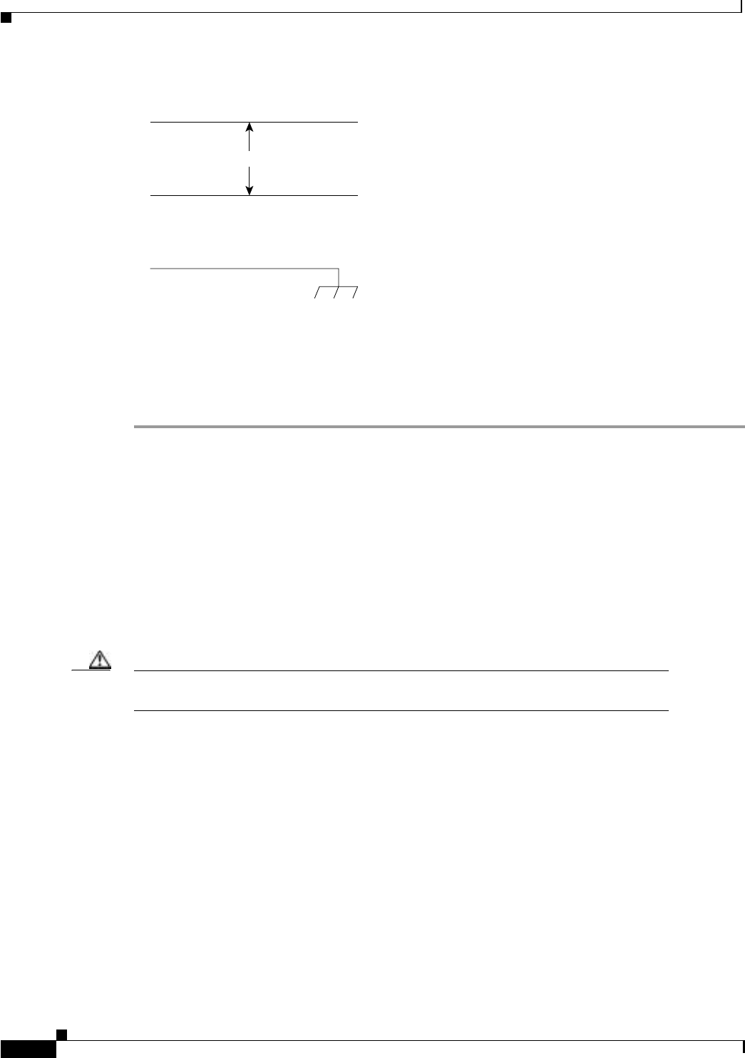
Caution For continued protection against risk of fire, replace only with the same type and rating of
fuse. Fuses should be replaced only after all power to the BPX switch has been turned off.
L1
180 - 240 VAC
L2
H10038