


29-6
Cisco BPX 8600 Series Installation and Configuration
Release 9.3.10, Part Number 78-11603-01 Rev. D0, July 2001
Chapter 29 Replacing Parts
Replacing a DC Power Entry Module
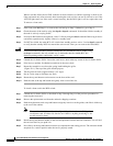
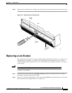
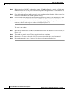
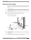
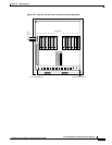
Figure 29-3 DC Power Entry Module with Conduit Box
Step 6
If a conduit box is used, remove it. Remove the ground screw above the middle terminal block
connector (see Figure 29-3).
Step 7 Remove the two standoffs on each side of the terminal block and pull the conduit box straight back. Set
it aside. Do not try to remove the terminal block.
Step 8 Loosen the two captive screws (at the bottom corners) holding the PEM. Loosen the two connector
jackscrews adjacent to the finger pull.
Step 9 Grasp the finger pull lip at the top of the PEM and pull the unit straight out.
Step 10 Replacement is the reverse of removal.
Conduit cover
screws
Conduit box
cover
CB1
ON
OFF
USE COPPER
CONDUCTORS ONLY
CB1
ON
OFF
USE COPPER
CONDUCTORS ONLY
+RTN –48V
90° terminal lug
(3 places)
H8005
Conduit connection
(customer supplied)
0
0