


CHAPTER
31-1
Cisco BPX 8600 Series Installation and Configuration
Release 9.3.10, Part Number 78-11603-01 Rev. D0, July 2001
31
BPX Switch Cabling Summary
This chapter specifies the cabling required to install the BPX switch:
• Trunk Cabling
• Power Cabling
• LM-BCC Cabling
• External Alarm Cabling
• Standard BPX Switch Cables
• Redundancy “Y” Cable
Note In all cable references:
The Transmit direction is from the BPX switch.
The Receive direction is to the BPX switch.
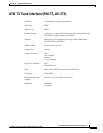
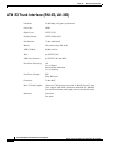
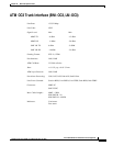
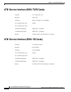
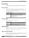
Trunk Cabling
Trunk cables connect the customer DSX-3 crossconnect point or T3-E3 Interface Module to the BPX
switch at the LM-3T3 back card. See Table 31-1.
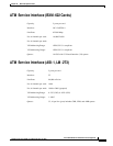
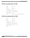
Table 31-1 Trunk Cables
Cable Parameter Description
Type: 75-ohm coax cable (RG-59 B/U for short runs, AT&T 734A for longer runs). Two
per T3/E3 line (XMT and RCV).
For European shipment of the BXM-E3 cards, in order to meet CE mark transient
test requirement (IEC1000-4-4), RG-17G double shielded SMB cable must be
used.
Max. Length: 450 feet max. between the BPX switch and the DSX-3/E3 point.
Connector: Terminated in male BNC; Rx is receive from trunk, Tx is transmit to trunk.