


20-8
Cisco BPX 8600 Series Installation and Configuration
Release 9.3.10, Part Number 78-11603-01 Rev. D0, July 2001
Chapter 20 Configuring Network Management
Configuring the LAN Port
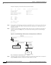
Example: Configuring a Control Port (Gateway Router Example)
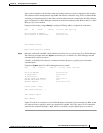
beta TN YourID.1 BPX 15 9.3 July 3 2000 02:16 PST
Active IP Address: 192.187.210.30
IP Subnet Mask: 255.255.255.0
IP Service Port: 5120
Default Gateway IP Address: 192.187.207.1
Maximum LAN Transmit Unit: 1500
Ethernet Address: 00.C0.43.00.00.20
Type State
TCP UNAVAIL
UDP READY
Telnet READY
This Command: cnflan
Enter IP Address:
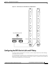
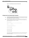
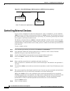
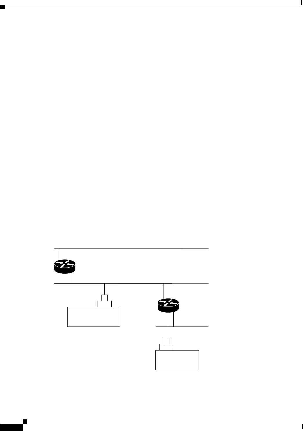
Step 3 Connect the Cisco WAN Manager workstation and the BPX switch to a LAN network. The LAN port
ontheBPXswitchprovidesaDB-15connectorthatcanbeconnectedtoaY-cablewhichinturnis
connectedtoanAUI.
Step 4 To test that a LAN connection to the BPX switch LAN port is okay, for example, for a host name of
“sanfran” enteredintheconfig.sv file, you would enter the following at the Cisco WAN Manager
workstation:
ping sanfran
Figure 20-3 Cisco WAN Manager LAN Connection via Gateway Router to a BPX Switch
Step 5
An IP Relay address must be configured for each node. The following example shows an example of
using the cnfnwip command to configure the IP Relay address for a node.
Note: IP addresses are representative, only.
Cisco WAN Manager
AUI
192.187.210.30
35746
192.187.207.200
BCC-LM
Sanfran
Default
gateway
192.187.207.11
193.287.107.1
Backbone
192.187.210.30
192.187.207.1