


2-14
Cisco uBR7200 Series Universal Broadband Router Software Configuration Guide
OL-2239-03
Chapter2 Configuring the Cable Modem Termination System for the First Time
Configuring the Cisco uBR7200 Series Using AutoInstall
Typically, the LAN interface and IP address are already configured on the existing router. You might
need to configure an IP helper address if the TFTP server is not on the same network as the new router.
In the following example, the existing router's configuration file contains the commands needed to
configure the router for AutoInstall on an Ethernet interface:
Router# more system:startup-config
. . .
interface Ethernet 0
ip address 172.31.10.1 255.255.255.0
ip helper-address 172.31.20.5
. . .
Using a Frame Relay-Encapsulated Serial Interface Connection
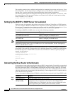
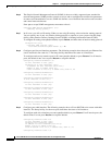
To set up AutoInstall via a serial line with Frame Relay encapsulation, you must configure the existing
router. Use the following commands beginning in global configuration mode:
You must use a DTE interface on the new router because the network always provides the clock signal.
In the following example, the existing router's configuration file contains the commands needed to
configure the router for Frame Relay AutoInstall on a serial line:
Router# more system:startup-config
. . .
interface serial 0
ip address 172.31.20.20 255.255.255.0
encapsulation frame-relay
frame-relay map ip 172.31.10.1 255.255.255.0 48
ip helper-address 172.31.20.5
. . .
Command Purpose
Step1
interface serial 0 Configures the serial interface that connects to the new router,
and enters interface configuration mode.
Step2
encapsulation frame-relay Configures Frame Relay encapsulation on the interface that
connects to the new router.
Step3
frame-relay map ip ip-address dlci
or
frame-relay interface-dlci dlci
option [protocol ip ip-address]
Creates a Frame Relay map pointing back to the new router.
or
For point-to-point subinterfaces, assigns a data link connection
identifier (DLCI) to the interface that connects to the new router,
and provides the IP address of the serial port on the new router.
Step4
ip address address mask Specifies an IP address for the interface. This step sets the IP
address of the existing router.
Step5
ip helper-address address Configures a helper address for the TFTP server.
Step6
_(_IREFOBJ:1006127_)
_clock rate bps
(Optional) Configures a DCE clock rate for the serial line,
unless an external clock is being used. This step is needed only
for DCE appliques.
Step7
Ctrl-Z Exits configuration mode.
Step8
copy running-config
startup-config
Saves the configuration file to your startup configuration.
Note On most platforms, this step saves the configuration to
NVRAM. On the Cisco 7000 family, this step saves the
configuration to the location specified by the
CONFIG_FILE environment variable.