


1-15
Cisco uBR7200 Series Universal Broadband Router Software Configuration Guide
OL-2239-05
Chapter1 Overview of Cisco uBR7200 Series Software
CiscouBR7200Series Router Configuration Overview
CiscouBR7200Series Router Configuration Overview
This section describes CiscouBR7200seriesrouter features that require software configuration, and
summarizes these features of the CiscouBR7200seriesrouter:
• Port Adapter and Line Card Slot and Logical Interface Numbering, page 1-15
• MAC-Layer Addressing, page 1-17
• Cable Interface Line Cards, page 1-17
• Cable Interface Line Card Slots, page 1-19
• Interfaces and Physical Ports, page 1-20
• Port Adapter Slots, page 1-20
Refer to the “Cisco uBR7200 Series Router Configuration Tools” section on page1-31 for additional
configuration utilities.
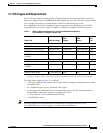
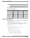
Port Adapter and Line Card Slot and Logical Interface Numbering
For Cisco uBR7200 series components, the slot number is the chassis slot in which a port adapter or a
cableinterface card is installed. The logical interface number is the physical location of the interface
port on a port adapter. Numbers on a Cisco uBR7200 series router begin with 0. Using a Cisco uBR7246
to illustrate, slot/port positioning is as follows:
• Slot 0—I/O controller
• Slot 1-2—Cisco port adapters
• Slot 3-6—Cisco cable interface line cards; the upstream ports on the card start with port 0.
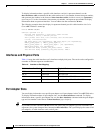
To configure the system, define the Cisco uBR7200 series interfaces, using the interface type slot/port
commands:
• Type—Cable
• Slot—Slot number in chassis. Slot numbers begin with 0.
• Port—Port number on a cable interface line card slot. Port numbers begin with a 0.
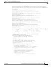
Configuring Cisco cable interface line cards is particularly important because these components serve
as the cable TV RF interfaces. Configuration involves the following tasks for each interface:
• Setting the downstream center frequency for the card to reflect the digital carrier frequency of the
downstream RF carrier (the channel) for that downstream port. To do this, enter the fixed center
frequency for your downstream RF carrier in Hz:
Router (config-int)# cable downstream frequency down-freq-hz
Note This command has no effect on the external upconverter, which actually sets the downstream
frequency. Noting the correct value for the cable interface line card, however, provides useful
information for troubleshooting.
The digital carrier frequency is specified to be the center of a 6 or 8 MHz channel based on your
channel plan. To illustrate for NTSC channel plans, EIA channel 95 spans 90.00 to 96.00 MHz. The
center frequency is 93.000 MHz which is the digital carrier frequency that should be configured as
the downstream frequency.