


3-27
Cisco uBR7200 Series Universal Broadband Router Software Configuration Guide
OL-2239-03
Chapter3 Configuring Cable Modem Interface Features
Configuring the Upstream Cable Modem Interface
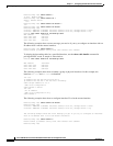
Router# show interface c5/0 sid 1 counters
00:02:23: %ENVM-3-LASTENV: Cannot save environmental data
Sid Req-polls BW-reqs Grants Packets Frag Concatpkts
issued received issued received complete received
1 0 22 22 22 0 0
2 0 3 3 2 0 0
3 0 0 0 0 0 0
Verifying Upstream Traffic Shaping
To determine if upstream traffic shaping is configured and activated, enter the show running-config
command and look for the cable interface configuration information. If upstream traffic shaping is
configured and enabled, a traffic shaping entry appears in the show running-config output. If upstream
traffic shaping is disabled, no cable upstream rate-limit appears in the output.
You can also perform the following tasks to verify that traffic shaping is enabled on the upstream channel:
Step1 Configure a low-peak upstream rate limit for the CM in its QoS profile. Either use the command-line
interface (CLI) to modify the modem’s QoS profile, or edit the modem’s TFTP configuration file. refer
to theDOCSIS 1.1 for the Cisco uBR7200 Series Universal Broadband Routers feature module on
Cisco.com.
Step2 Use a regular rate-limiting algorithm on the upstream without rate shaping, and note the drops of the
excess bandwidth requests from this CM when it exceeds its peak upstream rate.
Use the show interface cx/y sid counters verbose command to see the bandwidth request drops. Verify
that the upstream rate received by that modem is less than its configured peak rate, due to the timeouts
and backoffs produced by the drop in bandwidth requests. Enter the
showinterfacecx/y serviceflowqos command to see the input rate at CMTS in bps.
Step3 Enable grant shaping on the upstream channel by using the new shaping keyword extension to the
token-bucket algorithm CLI command.
Step4 Make the CM exceed its peak upstream rate by generating upstream traffic, and note the effect of grant
buffering (shaping) at the CMTS. If you use CM-to-CMTS pings, there is a perceivable decrease in the
frequency of the pings.
Let the pings run long enough to allow the averages at the CMTS to settle; then view the upstream rate
received by this single modem. Use the show interface cx/y command and see the input rate in bps. This
value should be close to the modem’s peak upstream rate. Also note the drop counts for the modem’s
SID by using the show interface sid counters command, and verify that the CMTS no longer drops the
bandwidth requests from the CM.
The bandwidth request drop count (from the previous nonshaping test) remains unchanged when
upstream rate shaping is used, indicating that the CMTS is actually shaping (buffering) the grants for the
modem. Verify that the input rate at the CMTS (from the single rate-exceeded CM) stabilizes close to
the configured peak rate of 128 Kbps.
Troubleshooting Tips
Perform these steps if you are having difficulty with verification:
Step1 Ensure that the cable connections are not loose or disconnected.
Step2 Ensure that the cable interface line card is firmly seated in its chassis slot.
Step3 Ensure that the captive installation screws are tight.
Step4 Verify that you have entered the correct slot and port numbers.
Step5 Verify that you selected a valid frequency for your router.