


3-11
Cisco uBR7200 Series Universal Broadband Router Software Configuration Guide
OL-2239-03
Chapter3 Configuring Cable Modem Interface Features
Configuring the Upstream Cable Modem Interface
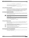
Building configuration...
Current configuration:
!
interface cable5/0
ip address 10.254.254.254 255.0.0.0
no ip directed-broadcast
cable helper-address 192.168.1.1
no keepalive
cable downstream annex B
cable downstream modulation 64qam
Perform these steps if you are having difficulty with verification:
Step1 Ensure that the cable connections are not loose or disconnected.
Step2 Ensure that the cable interface line card is firmly seated in its chassis slot.
Step3 Ensure that the captive installation screws are tight.
Step4 Verify that you have entered the correct slot and port numbers.
Step5 Verify that you selected the default if you are not certain about the modulation rate needed.
Step6 Verify that the downstream carrier is active using the cable downstream if-output command.
Configuring the Upstream Cable Modem Interface
These configurations are required. Upstream cable interface commands configure the frequency and input
power level of the upstream signal, in addition to error detection and correction of the upstream signal. The
configuration of the upstream cable interface depends on the characteristics of your cable plant.
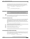
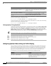
Perform the following tasks in this section to configure the upstream cable interface.
Note For some of these tasks, default values are adequate to configure the device.
Task Description
“Activating Upstream Admission
Control” section on page3-12
Provides information about the upstream admission control
feature, and provides instructions to set the upstream admission
control as a percentage of the upstream channel capacity.
“Activating Upstream Differential
Encoding” section on page3-13
Provides brief explanation and instructions to activate
differential encoding on the upstream, which is a digital
encoding technique whereby a binary value is denoted by a
signal change rather than a particular signal level.
“Activating Upstream Forward
Error Correction” section on
page3-14
Provides instructions to activate forward error correction
(FEC). The CiscouBR7200series CMTS uses FEC to attempt
to correct any upstream data that might have been corrupted.
“Activating the Upstream Ports”
section on page3-15
Provides instructions to activate upstream ports. Each upstream
port must be activated to enable upstream data transmission
from the CMs on the HFC network to the CiscouBR7200series
CMTS.