


Installing System Board Options 8-5
and delete the expansion card from the configura-
tion information.
See Chapter 5, “Using the System Configuration
Utility,” in the system User’s Guide for instructions.
NOTE: If you removed a PCI expansion card, the
system automatically performs any required re-
configuration tasks during the boot routine.
A
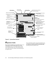
dding Memory
The 16 single in-line memory module (SIMM) sockets on
the memory module can accommodate 64 to 2048 mega-
bytes (MB) of dynamic random-access memory (DRAM).
The Dell PowerEdge 6100 systems use 72-pin, 36-bit buff-
ered SIMMs in these 72-pin sockets. The memory module
connector is located near the top edge of the system board
(see Figure 8-1).
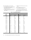
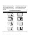
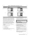
Memory Upgrade Kits
The system is upgradable to 2048 MB (2 gigabytes [GB])
by installing combinations of 16- or 64-MB single-sided or
32-MB or 128-MB double-sided SIMMs. The SIMMs
should be rated at 60 nanoseconds (ns) or 70 ns. Table 8-1
shows several sample memory configurations. Memory
upgrade kits can be purchased from Dell as needed.
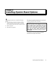
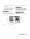
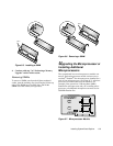
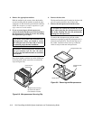
SIMM Installation Guidelines
The SIMM sockets are labeled “J1” through “J16” (see
Figure 8-4). Slots J1 to J8 make up bank 1; slots J9 to J16
compose bank 2.
Figure 8-4. Memory Module and SIMM Sockets
bank 2
J1
bank 1
bank 2
bank 1
J16