


9-4 Dell PowerEdge 6100/200 System Installation and Troubleshooting Guide
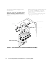
Most interface connectors are keyed for correct insertion;
that is, a notch or a raised tab on one connector matches a
tab or notch on the other connector. Keying ensures that
the pin-1 wire in the cable (indicated by the colored strip
along one edge of the cable) goes to the pin-1 ends of the
connectors on both ends.
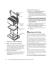
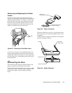
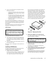
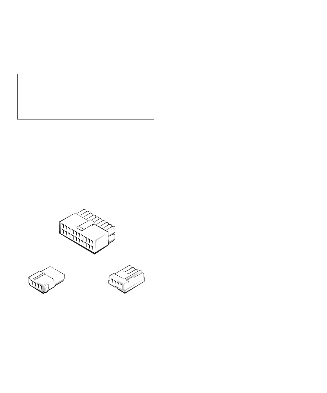
DC Power Cables
Each drive in the external drive bays must connect to a
4-wire DC power cable from the system power supply or
power-supply paralleling board. The connectors on this
cable are labeled “FD1,” “FD2,” “FD3,” “FD4,” and
“FD5.” Connectors FD1 through FD4 are used for
5.25-inch devices, whereas connector FD5 is used for the
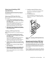
standard 3.5-inch diskette drive. Before connecting a
drive to a power cable, refer to Figure 9-5 to identify the
correct cable connector to use for the drive.
Figure 9-5. DC Power Cable Connectors
I
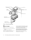
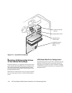
nstalling SCSI Devices in the
External Bays
SCSI devices in the external drive bay (such as CD-ROM
drives and tape drives) are controlled by the Ultra/Wide
SCSI controller on the system board.
SCSI Configuration Information
Although SCSI devices are installed essentially the same
way as other devices, their configuration requirements
are different. To configure SCSI devices installed in the
external bays, follow the guidelines in the following
subsections.
SCSI ID Numbers
Each device attached to the Ultra/Wide SCSI host adapter
must have a unique SCSI identification (ID) number
from 0 to 7.
When SCSI devices are shipped from Dell, the default
SCSI ID numbers are assigned as follows:
•
The computer’s built-in Ultra/Wide SCSI host
adapter is configured through the basic input/output
system (BIOS) as SCSI ID 7.
•
A SCSI tape drive is configured as SCSI ID 6 (the
default ID number for a tape drive).
•
A SCSI CD-ROM drive is usually configured as
SCSI ID 5.
NOTE: There is
no
requirement that SCSI ID numbers be
assigned sequentially or that devices be attached to the cable in
order by ID number.
Device Termination
SCSI logic requires that the two devices at opposite ends
of the SCSI chain be terminated and that all devices in
between be unterminated.
Before installing SCSI devices in the computer, you must
configure the terminators on the SCSI device(s) to con-
form to the following guidelines:
•
A single SCSI device (such as the standard
CD-ROM drive) is terminated.
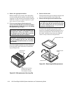
CAUTION: When connecting an interface cable,
do not reverse the interface cable (do not place the
colored strip away from pin 1 of the connector).
Reversing the cable prevents the drive from oper-
ating and could damage the controller, the drive,
or both.
system board
connector
5.25-inch drive
connector
3.5-inch drive
connector