


10006757-02 PmPPC7448 User’s Manual
i-3
Index
A
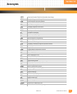
acronyms . . . . . . . . . . . . . . . . . . .12-1
address map, PCIO examples . . . . . 5-6
air flow rate. . . . . . . . . . . . . . . . . . . 2-9
B
baud rate generator (BRG) registers8-1
binary download format . . . . . . .11-25
block diagram
general system
. . . . . . . . . . . . . .1-3
monitor power-up . . . . . . . . . .11-3
board
configuration registers, CPLD
. . .7-6
product ID. . . . . . . . . . . . . . . . .2-12
product ID, PPMC . . . . . . . . . . .10-2
serial number . . . . . . . . . . . . . .2-12
boot
device JP2
. . . . . . . . . . . . . . . . .10-9
memory configuration . . . . . . . . 4-1
boot commands, monitor . . . . . .11-9
bus speed, PCI. . . . . . . . . . . . . . . .5-14
C
cable
Ethernet
. . . . . . . . . . . . . . . . . . .6-3
serial I/O . . . . . . . . . . . . . . . . . . . 8-2
cache, CPU memory . . . . . . . . . . . . 3-8
caution statements
board install/remove
. . . . . . . . .2-9
MV64460 PCI in reset . . . . . . . .5-14
setting the CPU configuration
register
. . . . . . . . . . . . . . . . . . . .5-2
USB connection . . . . . . . . .6-3, 8-3
writes to monitor area . . . . . . .11-4
circuit board dimensions . . . . . . . .2-1
compliance . . . . . . . . . . . . . . . . . . . 1-6
component map
bottom
. . . . . . . . . . . . . . . . . . . .2-3
DMC . . . . . . . . . . . . . . . . . . . . .10-2
top . . . . . . . . . . . . . . . . . . . . . . . 2-2
configuration registers, CPLD . . . . .7-6
connectors
Ethernet (P1) pin assignments
. .6-2
overview . . . . . . . . . . . . . . . . . . .2-4
overview, DMC . . . . . . . . . . . . .10-3
overview, PMC . . . . . . . . . . . . . .2-4
PCI pin assignments . . . . . . . . .5-10
serial (P2) pin assignments . . . . .8-2
contents, table of . . . . . . . . . . . . . .ii-iii
CPLD registers . . . . . . . . . . 7-1 to 7-7
CPU
block diagram
. . . . . . . . . . . . . . 3-2
cache memory . . . . . . . . .3-8, 3-10
exceptions . . . . . . . . . . . . . . . . . 3-6
features . . . . . . . . . . . . . . . . . . . 3-1
floating-point exception mode . 3-9
initialization . . . . . . . . . . . . . . . . 3-2
reference manual . . . . . . . . . . . . 1-8
reset . . . . . . . . . . . . . . . . . . . . . . 3-2
customer support. See technical
support.
D
development mezzanine card (DMC)
circuit board
. . . . . . . . . . . . . . .10-1
connectors . . . . . . . . .10-3 to 10-9
installation . . . . . . . . . . . . . . .10-11
jumpers . . . . . . . . . . . . . . . . . .10-9
LEDs . . . . . . . . . . . . . . . . . . . .10-10
setup . . . . . . . . . . . . . . . . . . .10-11
troubleshooting . . . . . . . . . . .10-13
DRAM . . . . . . . . . . . . . . . . . . . . . . . 4-2
reference manuals . . . . . . . . . . . 1-9
E
EIA-232 serial I/O port . . . . . . . . . . 8-2
Emerson identifier, Ethernet . . . . . 6-2
environment parameter commands,
monitor
. . . . . . . . . . . . . . . . . . . .11-17
environment variables . . . . . . . . .11-7
equipment for setup. . . . . . . . . . . . 2-8
eready register (ERdy) . . . . . . . . . . 7-5
ESD prevention. . . . . . . . . . . . . . . . 2-1
Ethernet . . . . . . . . . . . . . . . . . . . . . 6-1
address. . . . . . . . . . . . . . . . . . . . 6-2
connector and cable. . . . . . . . . . 6-2
F
features, overview . . . . . . . . . . . . . 1-1
figures, list of . . . . . . . . . . . . . . . . iii-vii
Flash . . . . . . . . . . . . . . . . . . . . . . . . 4-1
reference manual . . . . . . . . . . . . 1-9
Flash commands, monitor . . . . .11-14
G
grounding. . . . . . . . . . . . . . . . . . . . 2-1
H
hardware implementation dependent
registers (HIDx)
. . . . . . . . . 3-3 to 3-6
hardware version register (HVR) . . 7-6
I
I2C interface. . . . . . . . . . . . . . . . . . 8-2
device addresses . . . . . . . . . . . . 8-2
installation
DMC
. . . . . . . . . . . . . . . . . . . .10-11
PPMC . . . . . . . . . . . . . . . . . . . . 2-10
installation of the board. . . . . . . . . 2-8
interrupt enable register (IER) . . . . 7-4
interrupt pending register (IPR) . . . 7-4
interrupts, CPLD. . . . . . . . . . . . . . . 7-3
J
JTAG
COP interface
. . . . . . . . . . . . . . 10-7
CPLD programming interface . 10-8
DMC block diagram . . . . . . . . . 10-7
MV64460 PMC diagram. . . . . . 5-10
jumpers, DMC . . . . . . . . . . . . . . . 10-9
L
L1 and L2 cache . . . . . . . . . . . . . . 3-11
LEDs . . . . . . . . . . . . . . . . . . . . . . . . 2-5
DMC. . . . . . . . . . . . . . . . . . . .10-10
link port signal, PCI. . . . . . . . . . . . 5-12
M
machine state register (MSR). . . . . 3-8
mean time between failures (MTBF)1-6
memory
boot device
. . . . . . . . . . . . . . . . 4-1
commands, monitor . . . . . . .11-11
map, system. . . . . . . . . . . . . . . . 1-4
user Flash . . . . . . . . . . . . . . . . . . 4-1
Monarch. . . . . . . . . . . . . . . . . . . . 5-13
monitor
auto-booting
. . . . . . . . . . . . . . 11-1
auto-repeat . . . . . . . . . . . . . . . 11-1
basic operation . . . . . . . . . . . . 11-2
binary download format . . . .11-25
boot commands. . . . . . . . . . . . 11-9
command reference . . . . . . . . 11-8
command syntax . . . . . . . . . . . 11-9
command-line interface . . . . . 11-1