


Development Mezzanine Card: Debug/Status LEDs
PmPPC7448 User’s Manual 10006757-02
10-10
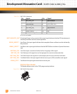
JP3: This is a user-defined jumper.
JP4: JP4 is the MV64460 serial ROM configuration jumper. If JP4 is installed, the MV64460 will
not try to configure from the serial ROM.
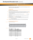
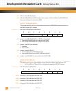
Jumper Setting Register
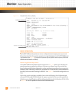
These read-only bits may be read by software at location F820,6000 to determine the cur-
rent DMC jumper (JP1) settings.
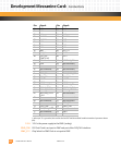
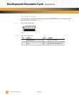
Register 10-1: DMC Jumper Setting Register at 0xf820,6000
JP4: Jumper 4 on DMC (MV64460 serial ROM configuration):
1 Installed (MV64460 will not configure from ROM)
0 Not installed (MV64460 will configure from ROM)
JP3: Jumper 3 on DMC (user defined):
1Installed
0 Not installed
JP2: Jumper 2 on DMC (BOOT):
1 Installed (Boot from DMC ROM socket)
0 Not installed (Boot from PmPPC7448 Flash-default)
JP1: Jumper 1 on DMC (ENET) is not used for the PmPPC7448.
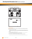
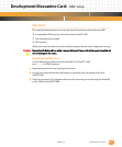
DEBUG/STATUS LEDS
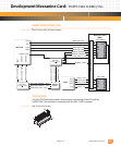
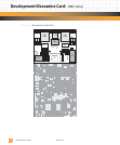
The DMC has four green, light-emitting diodes (LEDs) for software development; see
Fig. 10-1 for LED locations. These LEDs are controlled through the DMC LED register.
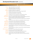
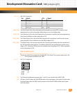
Register 10-2: DMC LED Register at 0xf820,d000
LED4: Asserting (1) this bit lights the DMC CR4.
LED3: Asserting (1) this bit lights the DMC CR3.
LED2: Asserting (1) this bit lights the DMC CR2.
LED1: Asserting (1) this bit lights the DMC CR1.
76543210
Reserved JP4 JP3 JP2 JP1
76543210
Reserved LED4 LED3 LED2 LED1