


Setup: PmPPC7448 Setup
PmPPC7448 User’s Manual 10006757-02
2-10
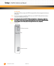
Installing the Module
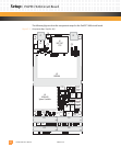
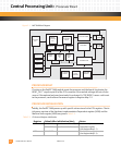
Most PPMC-compatible baseboards have two sets of four connectors (J11, J12, J13, J14 and
J21, J22, J23, J24), as defined by the PMC standard P1386.1. This allows the PmPPC7448 to
be installed in either PPMC slot.
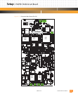
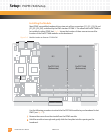
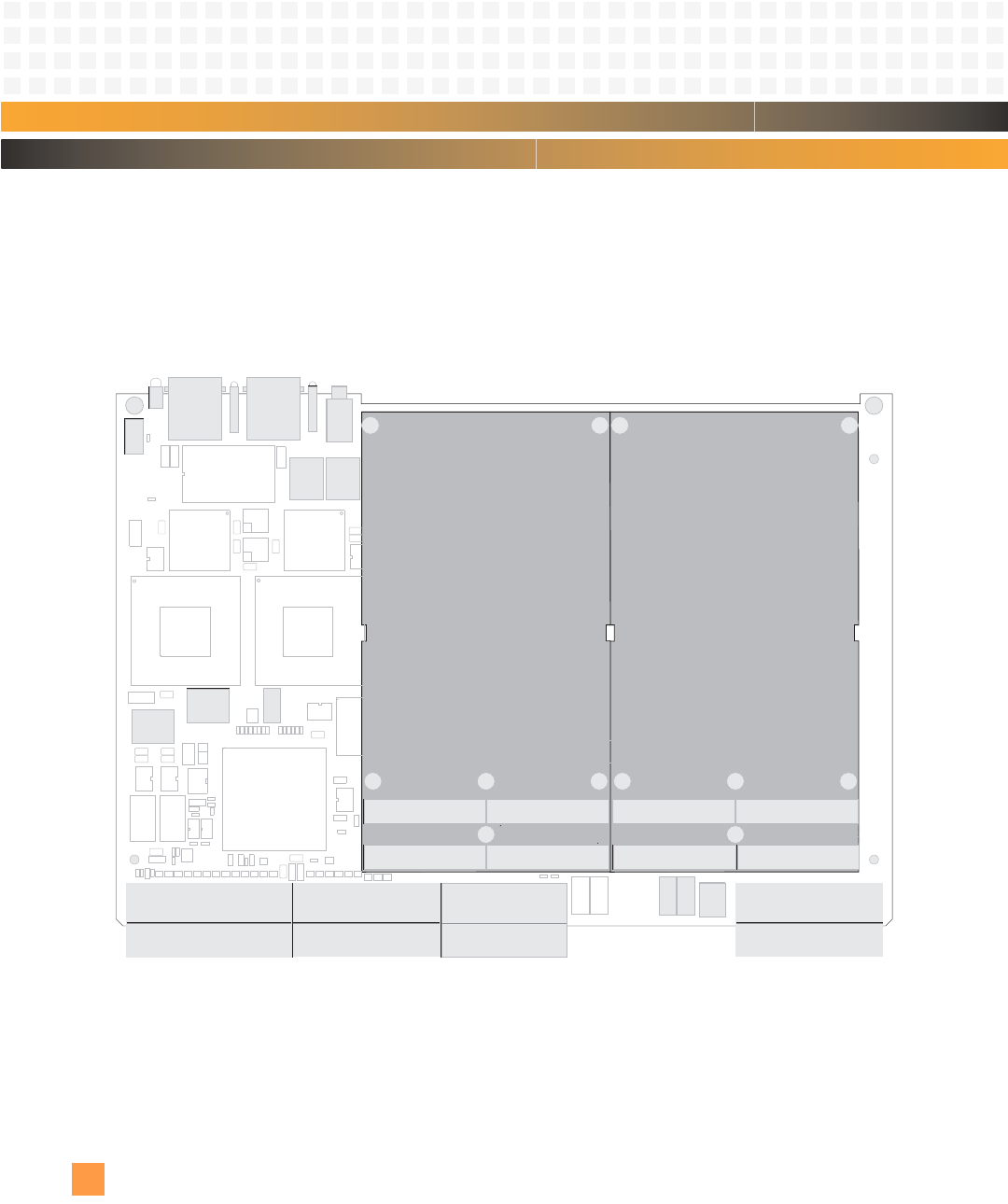
Fig. 2-6 shows the location of these connectors and the
location of the PmPPC7448 modules on the baseboard.
Figure 2-6: Module Location on Emerson CC1000-DM
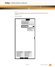
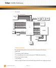
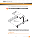
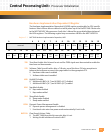
Use the following procedure to attach the PmPPC7448 module to your baseboard in slot
PMC1 (see
Fig. 2-7):
1 Remove the screws from the standoffs on the PPMC module.
2 Hold the module at an angle and gently slide the faceplate into the opening on the
baseboard.
PmPPC7448
(Bottomside)
PmPPC7448
(Bottomside)
J21
J22
J23
J24
J11
J12
J13
J14
J5J3J2J1
PMC 1 PMC 2