


Development Mezzanine Card: PmPPC7448 to DMC JTAG
PmPPC7448 User’s Manual 10006757-02
10-8
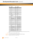
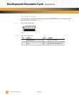
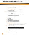
Table 10-4: DMC P3 Pin Assignments
2. Pin 14 is not installed.
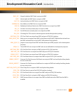
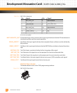
MPC7448 CKSTP_OUT*:Checkstop Output—when asserted, this output signal indicates that the CPU has detected a
checkstop condition and has ceased operation.
DEBUG_HRESET*: Hard Reset—this input signal indicates that a complete Power-on Reset must be initiated by
the processor.
DEBUG_SRESET*: Soft Reset—this input signal indicates that the MPC7448 must initiate a System Reset inter-
rupt.
MPC7448_TCK: Test Clock Input—scan data is latched at the rising edge of this signal.
MPC7448_TDI: Test Data Input—this signal acts as the input port for scan instructions and data.
MPC7448_TDO: Test Data Output—this signal acts as the output port for scan instructions and data.
MPC7448_TMS: Test Mode Select—this input signal is the test access port (TAP) controller mode signal.
DEBUG_TRST*: Test Reset—this input signal resets the test access port.
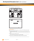
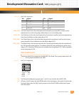
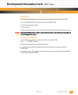
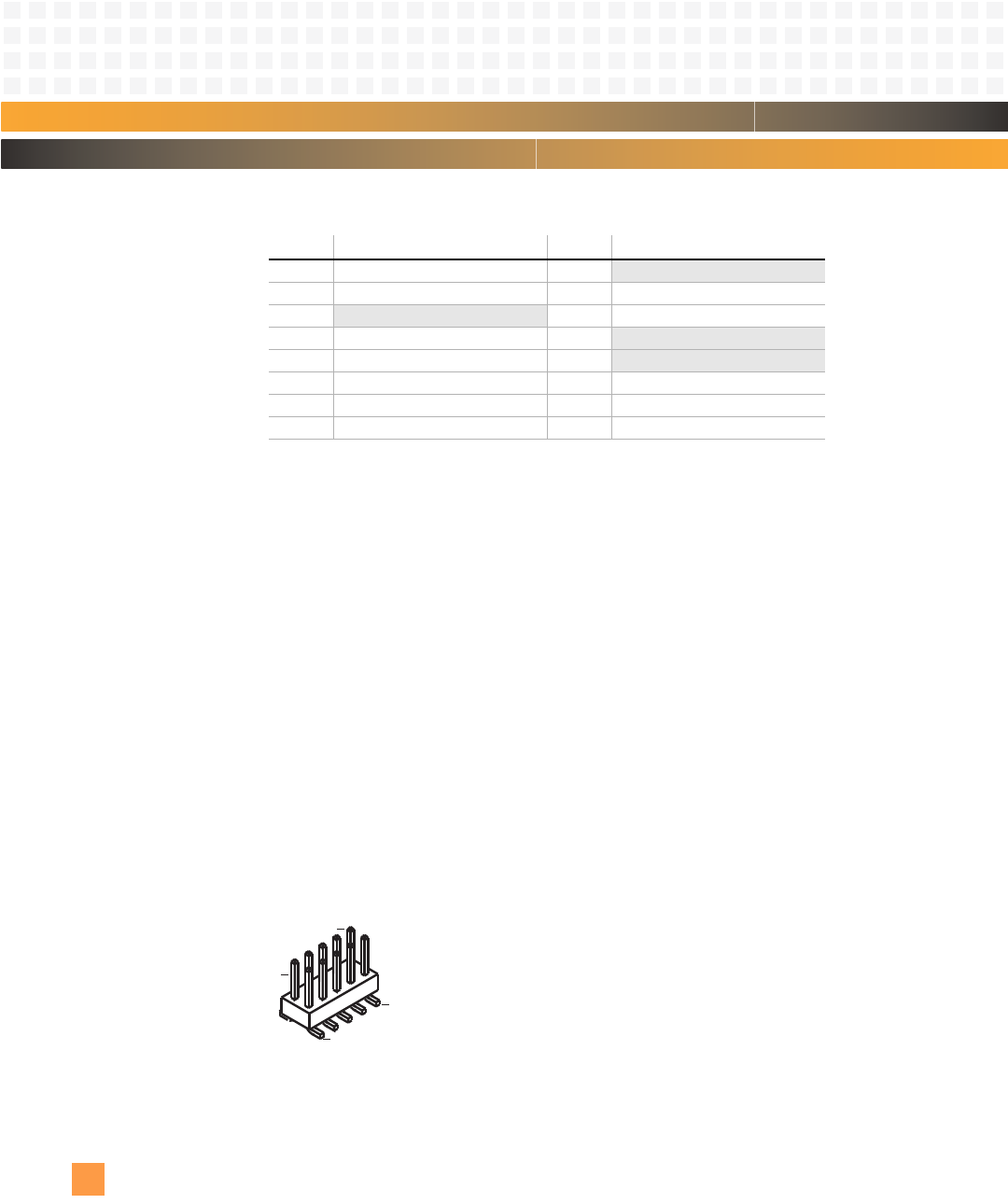
P4 JTAG Chain Header
This header allows access to the CPLD programming interface.
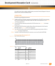
Figure 10-6: DMC P4 JTAG Chain Header
Pin: Signal: Pin: Signal:
1 MPC7448_TDO 2 Not connected
3 MPC7448_TDI 4 DEBUG_TRST*
5
Not connected 6 JTAG_PWR (1.8 V)
7 MPC7448_TCK 8
Not connected
9 MPC7448_TMS 10
Not connected
11 DEBUG_SRESET* 12 GND
13 DEBUG_HRESET* 14 Key
22
15 MPC7448CKSTP_OUT* 16 GND
1
2
9
10