


System Controller: PMC Connector Pinouts
PmPPC7448 User’s Manual 10006757-02
5-12
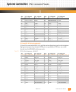
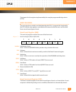
The following signals for the PCI interface are available on connector P14.
GPIOx: GENERAL PURPOSE INPUT OUTPUT These I/O signals (TTL) are connected to MV64460
MPP[19, 21:27]. At powerup (default), these pins are configured as inputs.
LPa_DX+/-, LPb_DX+/-: LINK PORT signals for Ethernet 10/100/1000 MDI
SERIALxTXD: SERIAL PORT 1-2 TRANSMIT DATA (Output to PMC, TTL or EIA-232)
SERIALxRXD: SERIAL PORT 1-2 RECEIVE DATA (Input to PMC, TTL or EIA-232)
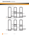
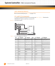
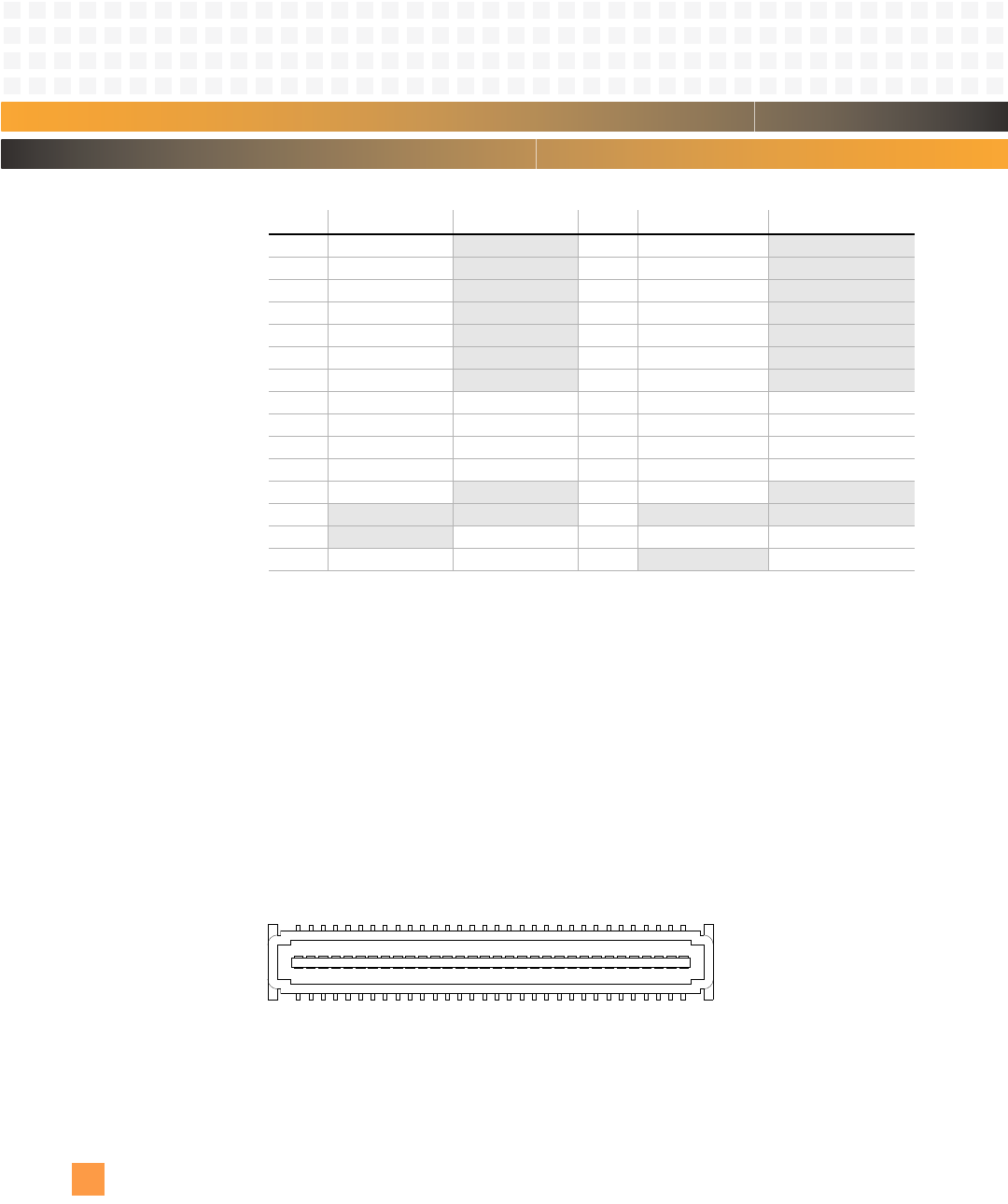
PMC Connector
Refer to the component map in Fig. 2-1 for the location of the PMC connectors on the
PmPPC7448 circuit board.
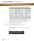
Figure 5-6: PMC Connector
35 AD47
Not connected 36 AD46 Not connected
37 AD45
Not connected 38 GND Not connected
39 V(I/O)
Not connected 40 AD44 Not connected
41 AD43
Not connected 42 AD42 Not connected
43 AD41
Not connected 44 GND Not connected
45 GND
Not connected 46 AD40 Not connected
47 AD39
Not connected 48 AD38 Not connected
49 AD37 GPIO0 50 GND GPIO1
51 GND GPIO2 52 AD36 GPIO3
53 AD35 GPIO4 54 AD34 GPIO5
55 AD33 GPIO6 56 GND GPIO7
57 V(I/O)
Not connected 58 AD32 Not connected
59
Not connected Not connected 60 Not connected Not connected
61
Not connected Serial1 TxD 62 GND Serial1 RxD
63 GND Serial2 TxD 64
Not connected Serial2 RxD
Pin: P13 Signal: P14 Signal: Pin: P13 Signal: P14 Signal:
1
2
63
64