System Controller: PMC Connector Pinouts
PmPPC7448 User’s Manual 10006757-02
5-10
PMC CONNECTOR PINOUTS
Each connector has 64 pins (see Fig. 5-6 on page 5-12).
P11 and P12 Pin Assignments
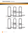
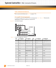
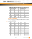
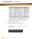
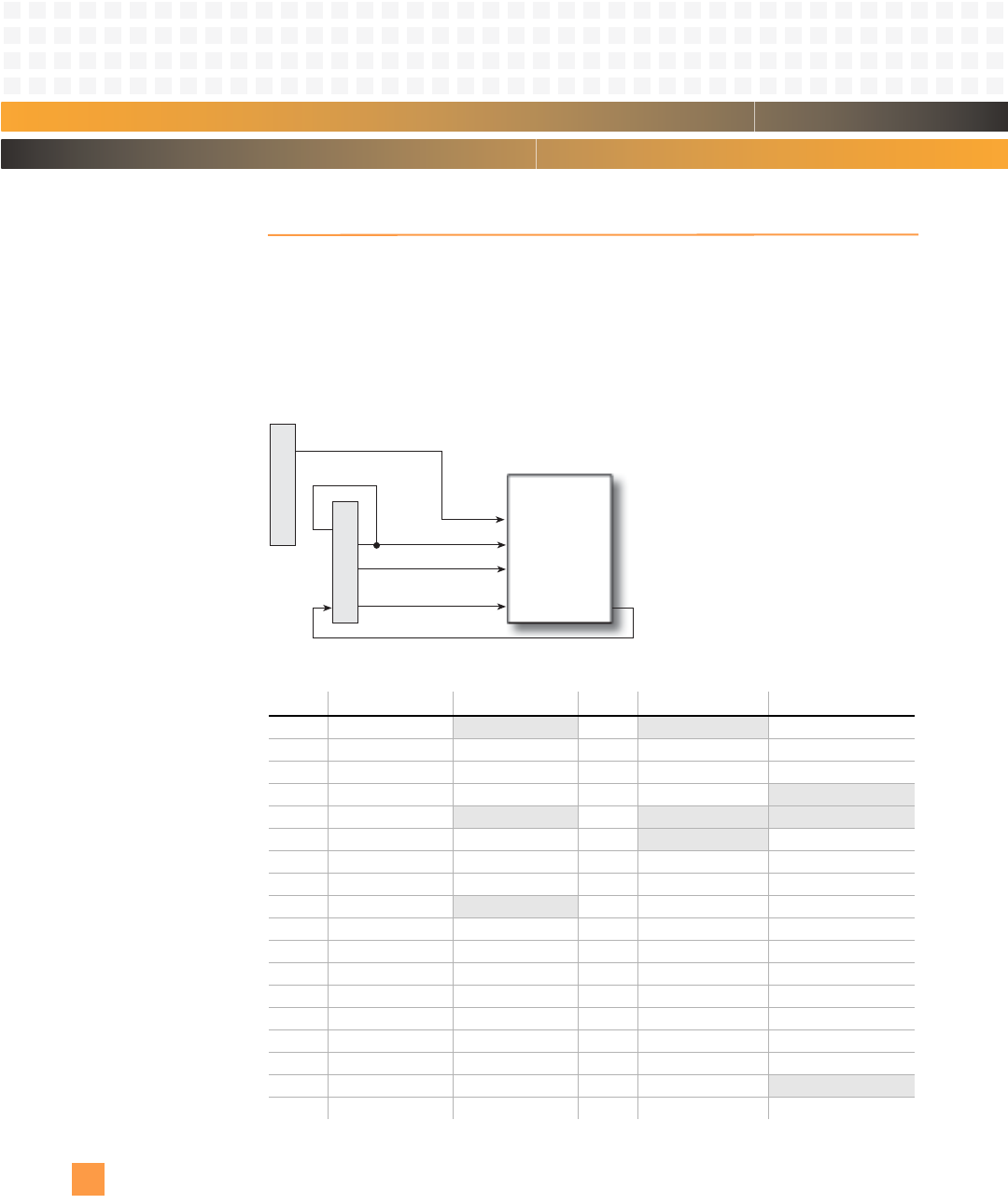
P11 and P12 support the 32-bit PCI bus connectors (see Table 5-1). Fig. 5-5 illustrates the
MV64460 JTAG signals routed from connector P12.
Figure 5-5: PCI JTAG Block Diagram
Table 5-1: P11/P12 Pin Assignments—32-Bit PCI
Pin: P11 Signal: P11 Signal: Pin: P11 Signal: P12 Signal:
1MV_TCK Not connected 2 Not connected MV_TRST*
3 GND MV_TMS 4 INTA* MV_PMC_TDO
5 INTB* MV_PMC_TDI 6 INTC* GND
7 PRESENT*/GND GND 8 +5 V
Not connected
9INTD*
Not connected 10 Not connected Not connected
11 GND PUP0 (pull up) 12
Not connected +3.3 V
13 PCI_CLK RST* 14 GND PDN0 (pull down)
15 GND +3.3 V 16 GNT* PDN1 (pull down)
17 REQ*
Not connected 18 +5 V GND
19 V(I/O) AD30 20 AD31 AD29
21 AD28 GND 22 AD27 AD26
23 AD25 AD24 24 GND +3.3 V
25 GND IDSEL 26 C/BE3* AD23
27 AD22 +3.3 V 28 AD21 AD20
29 AD19 AD18 30 +5 V GND
31 V(I/O) AD16 32 AD17 C/BE2*
33 FRAME* GND 34 GND
Not connected
35 GND TRDY* 36 IRDY* +3.3 V
P12
MV64460
TCK
TRST*
TMS
TDI TDO
PMC_MV_TCK
PMC_MV_TMS
PMC_MV_TRST*
PMC_MV_TDI
PMC_MV_TDO
PMC_VIO
P11


