


CPLD: Interrupt Registers
10006757-02 PmPPC7448 User’s Manual
7-3
SW: Software
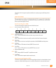
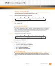
PCI reset driven when on-board hard reset is caused by a write to the Reset Command regis-
ter.
1Enabled
0Disabled
WD: WatchDog
PCI reset driven when on-board reset is caused by a timeout of the WatchDog timer.
1Enabled
0Disabled
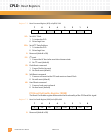
COPH: Hard RESET
PCI reset driven when reset is caused by a COP HRESET.
1Enabled
0Disabled
PCI0: PCI reset driven when on-board reset is caused by the assertion of PCI0 reset (PCI RESET).
1Enabled
0Disabled
FP: Front Panel
PCI reset driven when on-board reset is caused by the front panel pushbutton.
1Enabled
0Disabled
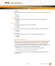
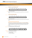
INTERRUPT REGISTERS
The system error and parity error interrupts are routed to the CPLD. These signals, per the
PCI specification, are sampled on the rising edge of the PCI clock. Since the PCI clock is
restricted to one load, SERR and PERR from the PPMC site are sampled with a 66 MHz on-
board clock. These signals should be held low for a clock cycle or they will be ignored. The
following signals are routed to the appropriate MV64460 MPP pin:
• PERR and SERR are combined into a single interrupt and routed to MPP13.
• The non-maskable watchdog timer is routed to MPP18.
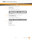
To control the routing of the interrupts, the CPLD implements the following enable and
pending registers.