


Setup: PmPPC7448 Circuit Board
PmPPC7448 User’s Manual 10006757-02
2-4
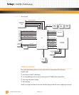
Connectors
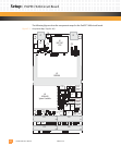
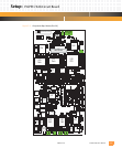
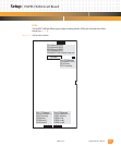
The PmPPC7448 has the following connectors:
P1: This mini-USB (universal serial bus) is the connection to the front panel 10/100 PHY Ether-
net (port 2). Refer to
Table 6-2 for the pin assignments.
P2: P2 is a mini-USB connector for the front panel serial port. Refer to
Table 8-2 for the pin
assignments.
P3: This is an 80-pin PCB-to-PCB male connector on the bottom side of the PmPPC7448. P3
routes memory, CPLD, and CPU signals from the PmPPC7448 to the DMC for development
use. See
Table 10-2 for the pin assignments.
P11, P12, P13: These 64-pin connectors provide the standard 64-bit PCI interface between the
PmPPC7448 and the PMC host. See
Table 5-1 for pinouts.
P14: This 64-pin connector conforms to the PCI specification as user-defined. Ethernet signals
are also available at P14. See
Table 5-2 for pinouts.
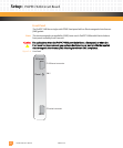
U3: This is the socket for the small-outline, dual inline memory module (SO-DIMM). The SO-
DIMM board layout depends on the memory configuration and manufacturer.