


Central Processing Unit: Processor Reset
PmPPC7448 User’s Manual 10006757-02
3-2
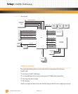
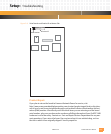
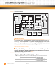
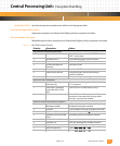
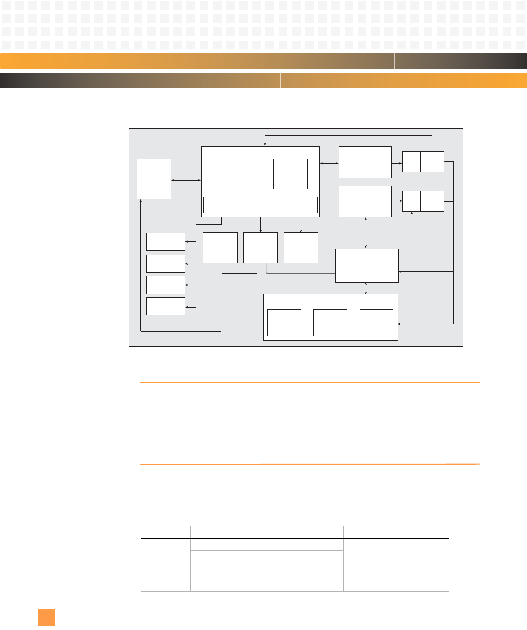
Figure 3-1: MPC7448 Block Diagram
PROCESSOR RESET
Circuitry on the PmPPC7448 module resets the processor and the board. It activates the
RESET_OUT* signal on pin 60 of the P12 connector if the module voltages fall out of toler-
ance or if the optional on-board reset switch is activated. A COP SRESET causes a soft reset
to the processor, see the Reset Command register in Register Map 7-2.
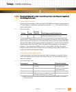
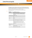
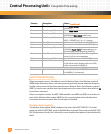
PROCESSOR INITIALIZATION
Initially, the PmPPC7448 powers up with specific values stored in the CPU registers. The ini-
tial power-up state of the Hardware Implementation Dependent register (HID0) and the
Machine State register (MSR) are given in
Table 3-2.
Table 3-2: CPU Internal Register Initialization
Register: Default After Initialization (Hex): Notes:
HID0 8000,0000 (icache and dcache off) Hardware Implementation
Dependent register
(See Register Map 3-1)
8000,C000 (icache and dcache on)
MSR 0000,B032 Machine State register
(See Register Map 3-3)
Memory Subsystem
System Bus
Interface
1 MB L2
Cache
Controller
L1 Service
Queues
Floating
Point
Unit
Instruction MMU
Data MMU
Tags
32-KB
D Cache
Tags
32-KB
I Cache
Integer
Unit 2
Integer
Unit 1
(3)
Completion
Unit
Branch
Processing
Unit
Instruction
Queue
VR Issue GPR Issue FPR Issue
Instruction Unit
Load/Store Unit
Vector
Permute Unit
Vector Integer
Unit 2
Vector Integer
Unit 1
Vector FPU