


EPSON Stylus Scan 2500 Revision A
Disassembly & Assembly Disassembling the Printer Mechanism 106
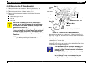
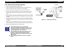
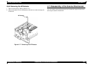
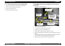
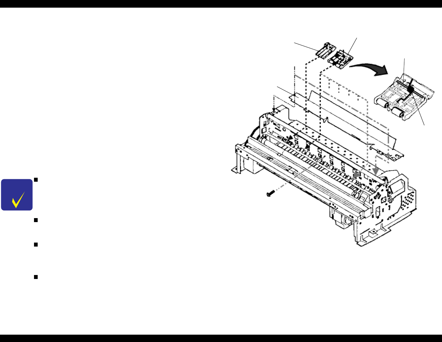
4.6.6 Removing the PF Roller Assembly
1. Remove the housing. (Refer to Section 4.3.)
2. Remove the carriage assembly. (Refer to Section 4.6.5.)
3. Remove three screws (CBS 3x6) on the printer mechanism and
disassemble the cable guide board.
4. Remove six upper paper guide assemblies, releasing their springs from
the hooks in the frame.
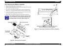
5. Remove the front paper guide ;B, releasing the hooks. (Refer to next
page.)
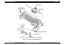
6. Remove the paper eject roller assembly, releasing the fixed locks located
on the right and left edges of the shaft.
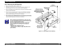
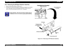
7. Release the fixed hook located on the left side of the PF roller assembly
shaft and rotate it so that the protrusion on the shaft (white) and hole for
receiving the shaft in the frame align.
8. Slide the PF roller assembly to the right and pull it out.
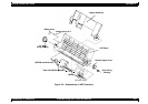
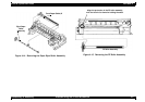
Figure 4-13. Removing the Paper Guide Assembly
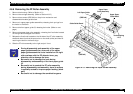
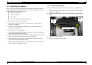
CHECK
POINT
During disassembly and assembly of the upper
paper guide assemblies, since one of the upper
paper guide assemblies to be installed on the right
side overlaps with the PE detector lever, pay
attention not to damage the lever.
Be careful not to damage the hook during
disassembly and assembly of the front paper guide
;B.
Be careful not to scratch the PF roller assembly
during disassembly and assembly, since its surface
is specially coated to improve paper feeding. (black
part)
Be careful not to damage the combination gears.
Upper Paper
Guide Assembly
Left Paper Guide
Cable Guide Board
(CBS 3x6)
(6 positions)
Upper Paper
Guide Shaft
Torsion Sprin
g
117.5
(CBS 3x6)