EPSON Stylus Scan 2500 Revision A
Disassembly & Assembly Disassembly of the Scanner Mechanism 110
4.7.1 Removing the scanner
You only need to remove the scanner from the scanner support frame when
replacing the scanner mechanism. You do not need to remove the scanner
from the support frame when servicing
The printer mechanism
The circuit boards
Any motors
Scanner parts such as the glass and lamp.
To remove the scanner, see the following.
1. Remove the rear cover and top cover as described in “Removing the
Housing” on pag e82.
2. Pull out the circuit board tray as described in “Removal of the Circuit
Board Tray” on pag e90.
3. Disconnect the scanner FFC (CN14).
4. Remove two screws (CBS 3x6) securing the tension spring and base and
unhook one end of the tension spring.
5. Remove the CR belt by pushing in the tension spring end and rotating the
belt while pulling it laterally away from the driven pulley.
6. Flip the scanner over so that it is upside down and resting on the ASF.
Use pliers to remove the CR belt clamp.
7. Slide the scanner CR guide shaft out of the bracket and slide the scanner
off the free end of the CR guide shaft.
4.7.1.1 Removing the lamp
You do not have to remove the scanner mechanism to replace the lamp.
1. Remove the rear cover and top cover as described in “Removing the
Housing” on page 82.
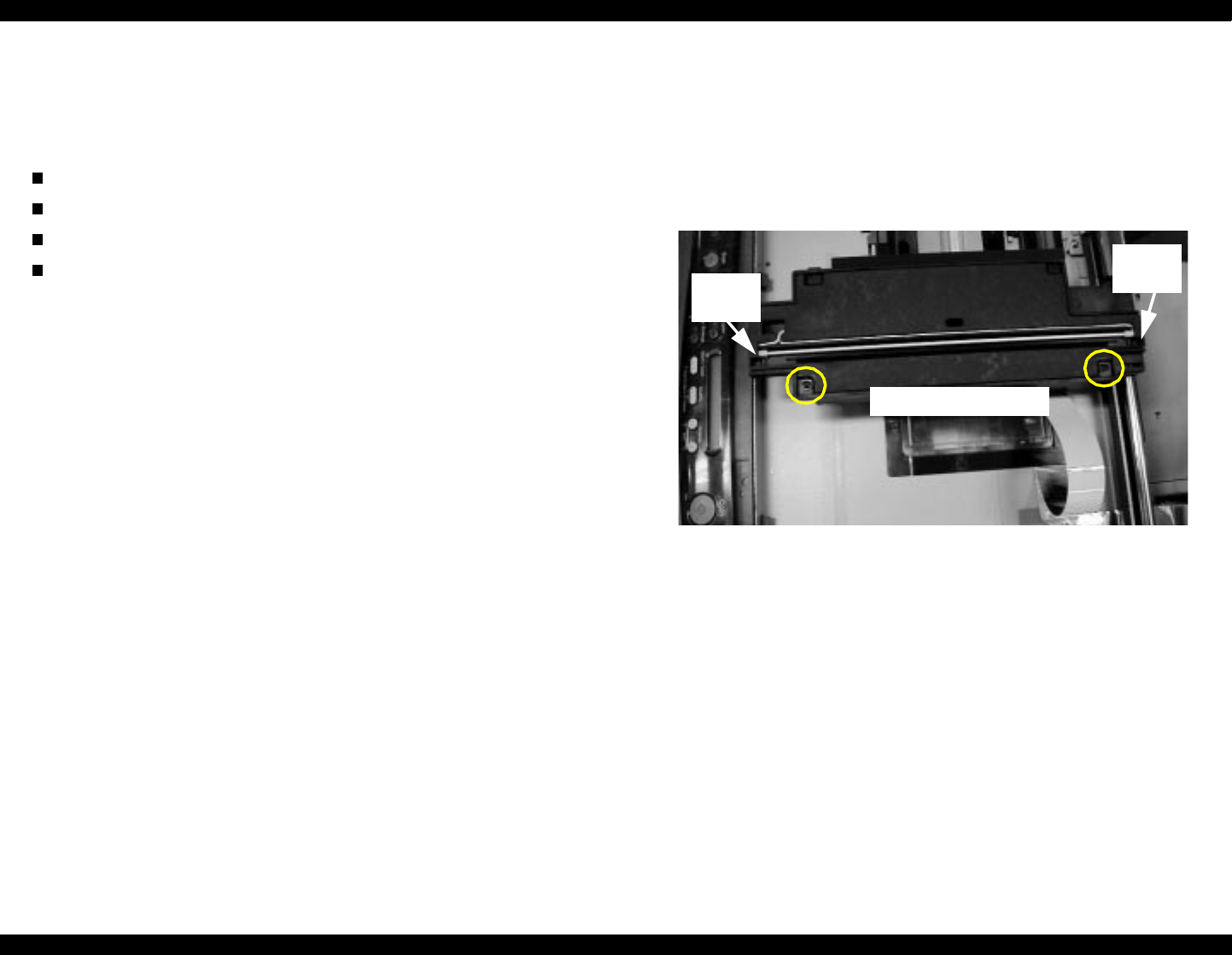
2. Remove two black screws (CBP 3x8 with flange) securing the scanner
cover.
3. Lift the cover by the sides.
4. Remove one connector from CN2.
Remove two screws.
Lift
here.
Lift
here.


