


EPSON Stylus Scan 2500 Revision A
Disassembly & Assembly Removing the Housing 84
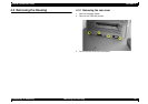
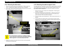
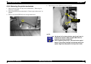
4.3.4 Removing the side covers
1. Remove the rear and top covers as described in “Removing the rear
cover” on page 82 and “Removing the top cover” on page 83.
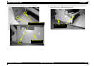
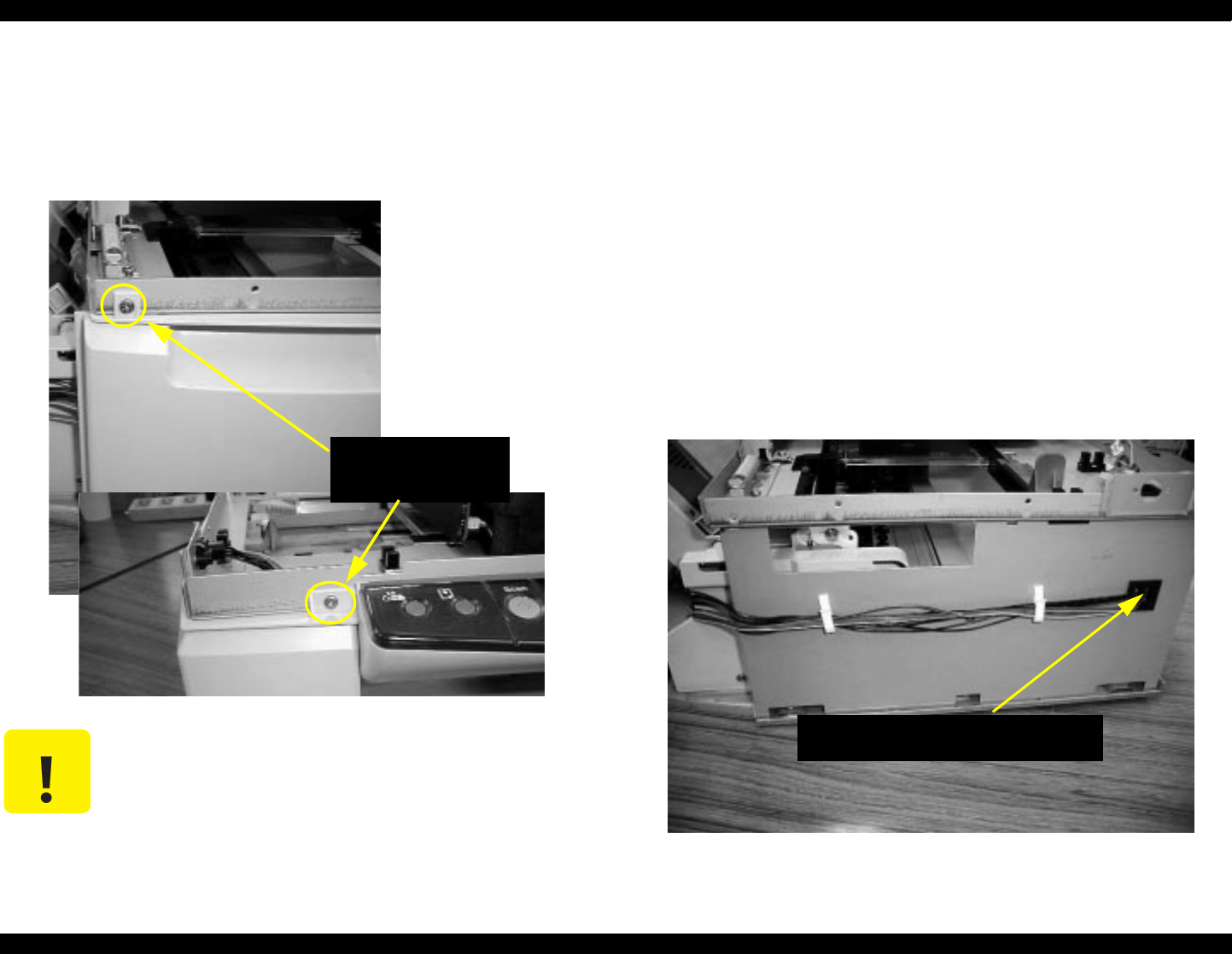
2. Remove two screws (CBS 3x6) securing the left-side cover and remove
the cover by pulling out and up from the top.
3. Repeat this process for the right-side cover after removing the paper-
thickness lever handle (blue).
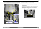
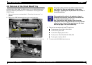
4.3.5 Removing the scanner support frame
To access the printer mechanism, printer motors, waste ink pads, or the B102
Power Supply board, you need to remove the scanner support frame. You
only need to remove the scanner from the scanner support frame when
servicing the scanner mechanism.
1. Remove the rear cover and top cover as described in “Removing the
Housing” on page 82.
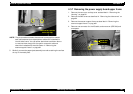
2. Pull out the circuit board tray as described in “Removal of the Circuit
Board Tray” on pag e90, and remove the scanner FFC (CN14). Also
remove the CN11, CN12, and CN15 connectors.
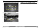
3. Remove the side covers as described in “Removing the side covers” on
page 84.
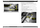
4. On the left side of the Stylus Scan pull the Scanner HP sensor cable,
Maintenance-cover-open cable, and Option-interface cable through the
clips and hole in the left-side frame.
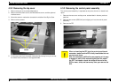
CAUTION
Be very careful when removing or replacing the side
covers. The hooks at the bottom are precisely positioned,
and forcing them in or out can easily break them.
Remove one screw
in front and one
Pull the cables out of the clips and out
through the other side of this hole.